page 7
MAN#650265
A temp sensor and an oil pressure sensor along with the needed hardware and harness to install them are an optional
accessory package (SEN-24-1) for the gauge. These provide additional gauge functions that are not included on the stock
RZR gauge. If this sensor pack is installed, the display of these gauge values needs to be enabled. To do so, enter the
setup menu and select the “
” menu. Then select the “
TEMP OIL
” option and change the setting from “
” to
“
”.
ENGINE CODE READOUT
As with the stock gauge, the UTV-1500 provides a readout of engine codes when the key is cycled from off-on-off-on-off-
on. Engine codes will flash on the check engine light and the message center will display “
” until a complete engine
code is received. Each received code number will then be displayed in the message center. When the end of the engine
code list is reached, “
” will be displayed. If no engine codes are available, “
” will be displayed right away.
FUEL GAUGE
This gauge has two fuel gauge displays. The primary display is a bar graph along the bottom of the gauge. This displays
the fuel level relatively between empty and full. The second is a percentage of full reading accessed in the message
center using the switch. At a reading of approximately %10 the fuel bar will begin to flash as a warning. Also the percent
full reading will be displayed in the message center. Pressing the switch will allow the message center to return to other
displays. The fuel bar will continue to flash until fuel is added. For some applications, there is no fuel sender and so there
is no fuel gauge data available. For these applications, the fuel gauge display can be disabled using the “
FUEL
”
option in setup.
DIAG MENU
Some diagnostic options are available in the setup routine to allow checking certain inputs to the gauge. The “
” option
will display the resistance in ohms seen at the gear sender input. This can be used to troubleshoot problems with the gear
sender. The “
” option provides a readout of the current flowing in the 4x4 coil in amps. This can be used to
troubleshoot problems with the 4x4 coil wiring and dashboard switch. Refer to the vehicle’s service manual for
troubleshooting guidance.
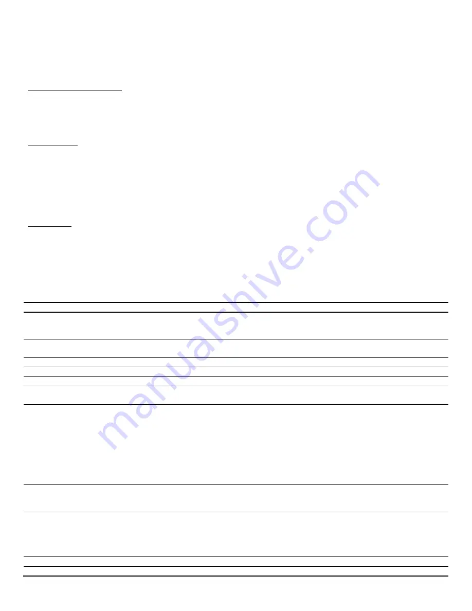
TROUBLESHOOTING
PROBLEM
CAUSE
SOLUTION
Gauge does not light up
Gauge has bad ground or power
Check connections to wiring harness and check
wiring harness and gauge wires for pinched or
broken wires.
Tach bar always stays
blank
Tach wire is not connected properly
Engine value set incorrectly
Check for good connection to main harness
Set Engine value to 12 for stock installation
Tach reads incorrectly
Engine value set incorrectly
Set Engine value to 12 for stock installation
Speed reads incorrectly
Speedometer needs to be recalibrated
See setup for speed calibration instructions.
Gauge does not dim
Dim level is set to off or set too low
Set dim level to higher level (see setup)
Gauge is always dim
Dim level is set too high
Light sensor right of speed is covered
Set dim level to lower level (see setup)
Make sure right side of lens is not covered.
is displayed in oil, or
water display
No sender connected, or incorrect
sender selected.
Check proper connection to sender. Check for
broken or pinched sensor wires.
For water temp sender, check for good ground
and remove any sealant tape on threads of
sender.
If temp and oil senders are not installed, temp and
oil display can be disabled (see setup).
is displayed in fuel, oil
or water display.
Sensor wire is shorted to ground.
Check sensor wire harness for correct connection
to sensor. Check for pinched or broken sensor
wire harness.
Fuel bar always shows full
and fuel display reads “
”
Vehicle does not have a fuel sender.
Wiring to fuel sender is disconnected
or broken.
Disable fuel display using setup option.
Check connections to fuel sender and wiring
harness for loose connections or broken wires and
repair.
PROBLEM
CAUSE
SOLUTION
ENG
light is flashing and
Engine computer is indicating the
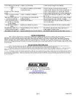
Turn engine off and allow to it cool. Determine and


