MAN 650314:D
17
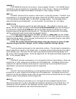
If “
Bus
” is selected for the sender type, the speed signal should be coming into the AUX
I/O port through the use of a BIM module. The adjustment ratio ranges from 75 – 125% on this
setting. It is assumed that the signal from the external device is the correct pulse rate, so there
are only provisions for slight adjustment. The LCD1 message will light up and show “
adjust
spD xxx%
”, XXX is adjustable from 75 – 125 and is the percentage the input is corrected by. If
set to 100 the signal is uncorrected and whatever the BIM module is reading is displayed on the
dash.
NOTES: For Adjust mode you can follow another vehicle, time yourself, or use a GPS as a
reference. A chassis dyno is another excellent way to use the Adjust mode.
Also be aware that the odometer is calculated from the speedometer cal value; if it is not
calibrated properly, odometer reading could be higher/lower than actual.
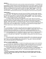
Service countdown meter (
Service
)
The service countdown meter allows you to set a distance value that will decrease as the
odometer increases. When the value gets to zero, a message “
Service DUE
” will appear on the
LCD1 message display on power up to remind you that service is due. This can be used for
routine maintenance reminders such as oil changes.
When “
service
” is displayed press and hold SW1 until the message screen changes.
Release the switch and the current service setting will be displayed.
Press and release SW1 to increase the value from “
OFF
” then “
500
”
-
“
7500
” in 500 mile
increments.
Once the desired setting is displayed, press and hold SW1 until “
DONE
” is displayed to
save the value.
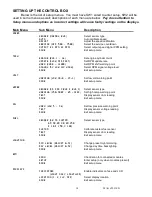
Speed Output (
OUTPUT
)
If a speed signal is needed for an ECM or cruise control, the SPD OUT terminal can be
used. This terminal can supply a 2,000 ppm or 4,000 ppm signal. If a BIM-01-1 is used to supply
the speedometer reading, this output is not available.
When “
output
” is displayed press and hold SW1 until the message screen changes.
Release the switch. The current PPM output will be displayed.
Press and release SW1 to toggle from “
2k PPM
” or “
4k PPM
”.
When the desired setting is displayed, press and hold SW1 until “
DONE
” is displayed.
Release the switch to go on to the next menu item.
Exit setup (
done
)
This will allow you to exit the speed setup and go on to the next setup menu.
When “
speed done
” is displayed, press and hold SW1 until you get “
DONE
”
Release the switch to go on to the next menu
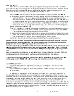
TACHOMETER SETUP
The control box can be set to read from 1-16 cylinder ignition signals. It can also be set to
read either 12 volt tach signals or 5 volt tach signals found on some engine computers. The
digital tachometer update rate can be adjusted between slow, mid, and fast. The RPM
warning/shift point can be adjusted from 2,200 – 14,800. The digital tachometer will read from
300 – 17,500 RPM, at RPM’s above 9,990 the reading will be displayed as RPMx10 in the
message center (12,000 RPM displays as 1,200).
You can also read the tach signal with the use of a bus interface module (BIM). Dakota
Digital offers the BIM-01-1 that will allow you to read the RPM from an ECU if you are installing
the system in a vehicle equipped with the OBDII diagnostic port or a drive train from a newer
vehicle. Most 1996 and newer vehicles have this.
Summary of Contents for VHX-69C-CAM
Page 40: ...MAN 650314 D 34...


