PZX-7
Ultrasonic Multi-Mode Thickness Gauge
7
Delay Line
Contact
The Transducer is the “business end” of the
PZX-7
. It transmits and receives
ultrasonic sound waves that the
PZX-7
uses to calculate the thickness of the material
being measured. The transducer connects to the
PZX-7
using a single shielded
coaxial cable with microdot connectors.
Delay Line Transducer
The single element delay line transducer is commonly used with the
PZX-7
for
materials with an approximate range of 0.006” to 1.00” in steel. The measurement
modes used with this style of transducer are echo-echo (E-E) and interface-echo (I-
E). Echo-echo mode will be used for the lower end of the measurement range, while
interface-echo for the upper end of the measurement range. Interface-echo mode
measures from the end of the delay line to the first return echo from the back wall of
the material, while echo-echo measurements are made between the first and second
return echoes from the back wall of the material. The frequency range for the
versions Dakota commonly supply are from 10MHz to 20MHz.
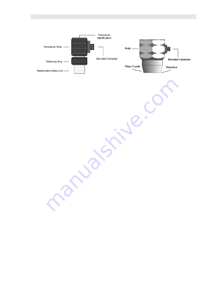
The Delay line is fastened to the transducer with a retaining ring. A drop of couplant
is applied between the delay line and transducer body. Refer to the diagram above.
The couplant should be checked on a regular basis to keep it from drying out. To
replenish, unscrew the retaining ring counterclockwise, separate the delay line from
the body, ‘clean both surfaces’, apply a drop of couplant, and reassemble.
Delay Line Graphite Tip (For use with Plastics Mode)
The
PZX-7
has a special “PLAS” mode that uses the standard delay line transducer,
as described above, but with a replaceable graphite delay tip. This mode and tip
should be used when the velocity of the plastic material measured is similar to the
velocity of the standard acrylic delay tip, and not achieving any signal/measurement.
The graphite tip creates a ‘mismatch’ between the tip material and the plastic material
measured.
The Delay line is fastened to the transducer with a retaining ring. A drop of couplant
is applied between the delay line and transducer body. Refer to the diagram above.
The couplant should be checked on a regular basis to keep it from drying out. To
Summary of Contents for PZX-7
Page 2: ......


