Dakota Ultrasonics
8
(size or frequency) for the material being measured. See page 13 for information on
transducer selection.
While the transducer is in contact with the material that is being measured, the
ZX-5
will perform four measurements every second, updating its display as it does so.
When the transducer is removed from the surface, the display will hold the last
measurement made.
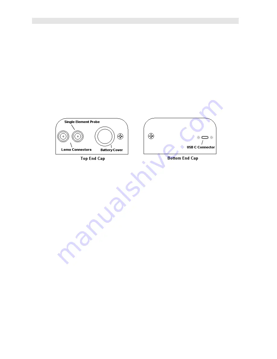
2.11 Top End Cap
The top end cap is where all connections are made to the
ZX-5
. The diagram above
shows the layout and description of the connectors:
Transducer Connectors
Refer to Diagram: The transducer connectors and battery cover/probe zero disk are
located on the
ZX-5’s
top end cap. The transducer connectors are of type Lemo
“00”.
Note:
There is no polarity associated with connecting the transducer to the ZX-5, it
can be plugged into the gauge in either direction.
Probe Zero Disk & Battery Cover
Refer to Diagram:
The Battery cover is the large round disk shown in the diagram.
Note:
This same disk is also used as a probe zero reference disk. Simply remove
the cover when replacing the batteries (2 AA cells). When performing a manual
probe zero function, simply place the transducer on disk making firm contact.
Important: Be sure the battery polarity is correct, which can be found on the back
label of the ZX-5.
Note:
Rechargeable batteries can be used, however they must be recharged outside
of the unit in a standalone battery charger.
Summary of Contents for Z-303-0001
Page 2: ......


