8
Basic Operation
2.4 Setting Radio Channels
Reference Drawings:
Channel Selection; Multiple Broadcast Group, Gen IV .........................
Drawing A-203113
Installation Details, Gen VI Channel Selection Guide .........................
Drawing A-1109870
The radio receiver units used in Daktronics scoreboards have a channel (CHAN) switch that
can be set from 1–8. The receivers also have a broadcast group (BCAST) setting. The
broadcast group defines a group of radio receivers that “listen” to the channel selected on the
channel switch as well as “listen” for data sent out on their broadcast channel.
Note:
The number of available broadcast groups varies depending on the generation of
radio receiver: Gen V radio receivers have 1–4, while Gen VI radio receivers have 1–8.
Each radio receiver will accept data sent from the broadcast channel of its respective
broadcast group, as well as data sent from the “Master Broadcast” channel. This is selected
when the console is set to BCAST 0 and CHAN 00.
In this type of system, the receiver unit at the scoreboard must have the channel switch set to
a specific channel. The operator must know which channel is selected in the scoreboard. The
operator must then enter the specific channel when prompted during console startup.
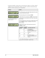
To determine the settings of a scoreboard, first
power it down and shut off any radio-
equipped consoles in the area. Next, power the
scoreboard back up and watch for the radio
settings. The settings will appear as “
bX CY
”
where
X
is the current broadcast group and
Y
is the current channel.
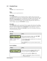
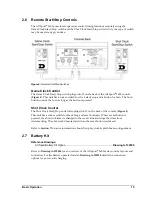
The settings are typically displayed in the clock
digits (
) or Home and Guest score
digits (
), depending on the scoreboard
model.
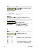
The console automatically detects when a
radio transmitter is installed and will prompt
the user for transmitter settings after a valid
sport code is entered.
Note:
If interference from a nearby Daktronics system is suspected, press
<CLEAR>
at
the “RADIO SETTINGS” prompt to change the channel number.
There are three different radio scenarios that can be accommodated: a single controller system,
a multiple controller system with a single broadcast group, and a multiple controller system
with multiple broadcast groups. These scenarios are described on the following pages.
Figure 4:
Radio Settings in Score Digits
Figure 3:
Radio Settings in Clock Digits
Summary of Contents for All Sport 1600 Series
Page 2: ......
Page 4: ......
Page 8: ......
Page 12: ......
Page 24: ......
Page 34: ......
Page 38: ......
Page 44: ......
Page 48: ......
Page 50: ......
Page 56: ......
Page 57: ......
Page 58: ......
Page 59: ......
Page 60: ......
Page 61: ......
Page 62: ......
Page 64: ......
Page 66: ......
Page 67: ...CLOCK SCORE LL 2496 R06 CODE 01 ALL SPORT 1000 2510 CODE 81 MS 2001...
Page 68: ...7 4 1 8 5 2 9 6 3 0 VOLLEYBALL ALL SPORT 1000 2510 CODE 82 MS 2001 LL 2502 R04 CODE 02...
Page 69: ...7 4 1 8 5 2 9 6 3 0 LL 2499 CODE 07 TIMER...
Page 71: ...7 4 1 8 5 2 9 6 3 0 LL 2498 CODE 06 SEGMENT TIMER...
Page 72: ...7 4 1 8 5 2 9 6 3 0 LL 2497 CODE 08 TENNIS B O T T O M P O T...
Page 73: ......
Page 74: ......
Page 76: ......
Page 77: ......
Page 78: ......
Page 79: ......
Page 80: ......
Page 88: ......
Page 90: ......


