All Sport 5100 Operation
1-7
1.9 Setting Radio Channels
Reference Drawings:
Installation: Outdoor,
Gen IV Radio Receiver..........................................
Drawing A-180514
Installation: Indoor,
Gen IV Radio Receiver..........................................
Drawing A-180521
Channel Selection;
Single Control Console, Gen IV ............................
Drawing A-180566
Channel Selection;
Single Broadcast Group, Gen IV ...........................
Drawing A-180922
Channel Selection;
Multiple Broadcast Group, Gen IV.........................
Drawing A-180923
Indoor LED Driver Update
For Gen IV Radio Receiver ...................................
Drawing A-181729
Refer to
Appendix A
for the Reference Drawings listed here.
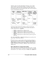
The radio receiver units used in the scoreboards have a channel setting switch that
can be set from 1 to 8 (channels 0, and 9-15 are not used.) A radio receiver will
accept data from a console transmitter with the same channel (and broadcast group)
setting.
The receivers also have a jumper that can be used to select broadcast group 1 or
broadcast group 2. A “Broadcast Group” defines a group of radio receivers that in
addition to “listening” to the channel selected on the channel switch will also
“listen” for data broadcast on their broadcast channel. There are a total of two
broadcast groups available.
Each radio receiver will accept data sent from the broadcast channel of its respective
broadcast group. This is selected by setting the transmitter (console) radio to
channel 0. Every radio receiver will also accept data sent from the “Master
Broadcast” channel. This is selected when a transmitter (console) radio is set to
Broadcast Group 0 (BCAST 0) and Channel 0.
The channel number and broadcast group set on the radio installed in each
scoreboard can be verified by cycling power to the scoreboard. Approximately
seven seconds after power up, the scoreboard will show the current channel in the
scoreboard clock digits. A CXX will first be shown where XX is the current radio
channel number. This will be followed by BXCY where X is the current broadcast
group and Y is the current channel number within this broadcast group.
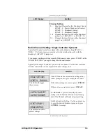
There are three different radio scenarios that can be accommodated.
1.
Single Controller System:
In a Single Controller system, all radio receivers and all scoreboards receive
signal from the same All Sport console at all times. The default channel
and broadcast group settings on the receiver are not typically modified. An
example of this type of system is a typical high school football installation.
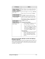
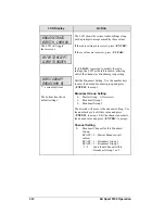
2.
Multiple Controller System With a Single Broadcast Group:
In a Multiple Controller system with a single broadcast group, there are
additional All Sport Controllers for controlling multiple scoreboards.
Summary of Contents for All Sport 5100
Page 1: ...All Sport 5100 Timer Operations Manual ED 12501 Rev 8 02 December 2003 ...
Page 2: ......
Page 36: ......
Page 54: ......
Page 64: ......
Page 72: ......
Page 76: ......
Page 79: ......
Page 80: ......
Page 81: ......
Page 82: ......
Page 83: ......
Page 84: ......
Page 85: ......
Page 86: ......
Page 87: ......
Page 88: ......
Page 89: ......
Page 90: ......
Page 91: ......
Page 92: ......
Page 93: ......
Page 94: ......
Page 95: ......
Page 96: ......
Page 97: ......
Page 98: ......
Page 99: ......
Page 100: ......
Page 101: ......
Page 102: ......
Page 103: ......
Page 104: ......
Page 106: ......
Page 108: ......
Page 110: ......
Page 112: ......
Page 114: ......
Page 116: ......
Page 118: ......
Page 128: ......
Page 134: ......
Page 135: ...Sport Code Labels G 1 Appendix G Sport Code Labels ...
Page 136: ......
Page 148: ......


