


Introduction
1
1 Introduction
This manual explains the installation and maintenance of Daktronics Transparent Shot
Clocks. For additional information regarding safety, installation, operation, or service,
refer to the telephone numbers listed in
Section 5: Daktronics Exchange and Repair &
. This manual is not specific to a particular installation. Project-
specific information takes precedence over general information found in this manual.
Important Safety Instructions
• Read and understand all instructions before beginning the installation process.
• Disconnect power to the display when not in use or when servicing.
• Disconnect power to the display before servicing power supplies to avoid electrical
shock. Power supplies run on high voltage and may cause physical injury if touched
while powered.
• Do not disassemble control equipment or electronic controls of the display; failure to
follow this safeguard will make the warranty null and void.
• Do not modify the structure or attach any panels or coverings to the display without
the express written consent of Daktronics.
• Do not drop the control equipment or allow it to get wet.
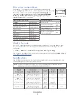
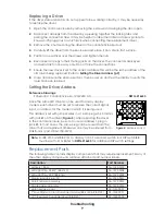
Specifications Label
Power specifications as well as serial and model number information can be found on an
ID label on the display, similar to the one shown in
ASSY NO.
SER. NO.
MFG DATE
BROOKINGS, SD 57006-5128
PHONE 800-325-8766
LL-2306 R01
201 DAKTRONICS DR.
DAKTRONICS
Figure 1:
Specifications Label
Please have the assembly number, model number, and the date manufactured on hand
when calling Daktronics customer service to ensure the request is serviced as quickly as
possible. Knowing the facility name and/or job number will also be helpful.
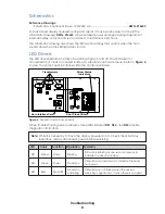
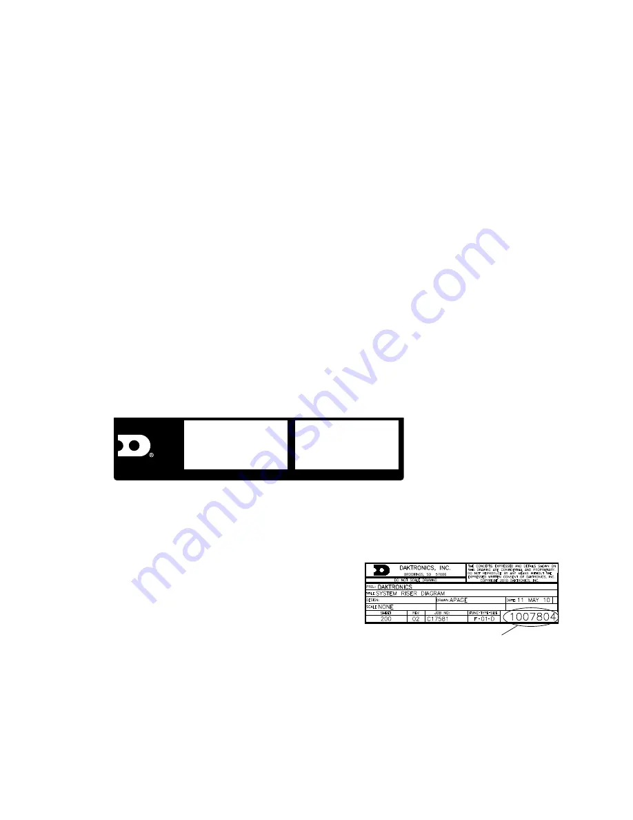
Resources
illustrates a Daktronics drawing label.
This manual refers to drawings by listing the last
set of digits. In the example, the drawing would
be referred to as
DWG-1007804
. All references to
drawing numbers, appendices, figures, or other
manuals are presented in bold typeface.
Any drawings referenced in a section are listed
at the beginning of it as shown below:
Reference Drawing:
System Riser Diagram .......................................................................................
DWG-1007804
Daktronics identifies manuals by the DD or ED number located on the cover page.
Ensure all applicable materials have been gathered before beginning the installation.
Contact a Daktronics sales coordinator or project manager.
Drawing Number
Figure 2:
Drawing Label
Summary of Contents for BB-2140
Page 4: ...This page intentionally left blank...
Page 18: ...This page intentionally left blank...
Page 19: ......
Page 20: ......
Page 21: ......
Page 24: ......
Page 25: ......
Page 26: ...AT EXPOSED TERMINALS HAZARDOUS VOLTAGE BEFORE SERVICING DISCONNECT POWER...
Page 27: ......
Page 28: ......
Page 31: ......
Page 32: ......
Page 33: ......
Page 34: ...This page intentionally left blank...