


Electrical Installation
5
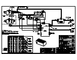
Signal Connection
Reference Drawings:
Connection Diagram: BB-2140 & BB-2141 .......................................................
DWG-184789
Connection Diagram; BB-2150 & BB-2151 .....................................................
DWG-1060264
Signal installation requires routing control cable from the control console to a signal
junction box (J-box) near the display, routing cable from the J-box to the control
enclosure, and routing the appropriate cables from the system components to the
control enclosure. At a minimum, use a paired, 22 AWG shielded cable (Daktronics part
# W-1077).
1�
Connect the cable to a 1/4" J-box at the control console end.
2�
Route the cable in conduit from the J-box on the control console end to a J-box near
the display.
3�
Install the 1/4" phone plug (part # 0L-40683) to the display end of the cable. Be sure
to connect the cable shielding only in the J-box on this end. DO NOT connect cable
shielding at the J-box near the control console.
4�
Insert the plug into the
J31 SIGNAL IN
jack on the front of the control enclosure.
5�
Connect the shot clock(s), remote horn enclosure, and any optional light strip kits to
the appropriate jacks on the control enclosure as shown in
DWG-184789
and
DWG-
1060264
.
6�
Connect a signal cable from the J-box to the
J1
,
J2
, or
J3
jack on the back of the All
Sport 5000 console.
Also connect the Shot Clock Start/Stop Switch (Daktronics part # 0A-1196-0031) to the
J7
jack on the All Sport 5000.
Radio Control
Radio control is an option for Daktronics shot clocks. The system provides scoreboard
control via a 2.4 GHz, extra-high frequency FM signal.
The radio transmitter and receiver are not standard equipment. This setup requires a
control console equipped with radio output as well as a radio receiver plugged into
the
J7
jack in the control enclosure and mounted internally to the front panel of the
enclosure.
Note:
A 5-pin to 6-pin adaptor (Daktronics part # W-2913) is required to connect newer
radio units to the shot clock driver.
For additional information about this option, contact a Daktronics representative. For
complete instructions on setting up radio control, refer to the
Gen VI Radio Installation
Manual (DD2362277)
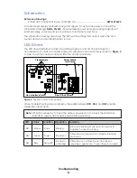
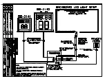
Light Strips
For installations that use LED backstop light strips, refer to the
LED End-of-Period Basketball
Lighting Display Manual (ED-13652)
, or the
BB-2135 Backboard LED Light Strips Display
Manual (ED-14187)
, both available online at
.
Summary of Contents for BB-2140
Page 4: ...This page intentionally left blank...
Page 18: ...This page intentionally left blank...
Page 19: ......
Page 20: ......
Page 21: ......
Page 24: ......
Page 25: ......
Page 26: ...AT EXPOSED TERMINALS HAZARDOUS VOLTAGE BEFORE SERVICING DISCONNECT POWER...
Page 27: ......
Page 28: ......
Page 31: ......
Page 32: ......
Page 33: ......
Page 34: ...This page intentionally left blank...


