


Troubleshooting
9
Replacing a Driver
If the driver status indicators do not appear to be working correctly, it may be necessary
to replace the driver.
1�
Open the control enclosure by removing the 6 screws and swinging the door open.
2�
Disconnect all plugs from the driver by squeezing together the locking tabs and
pulling the connectors free. It may be helpful to label the cables or take a picture to
know which plug goes to which jack when connecting the replacement driver.
3�
Remove the 4 nuts securing the driver to the control enclosure door.
4�
Carefully lift the driver from the enclosure and place it on a clean, flat surface.
5�
Position a new driver over the screws and tighten the nuts.
6�
Reconnect all plugs to their mating jacks on the driver. The connectors are keyed
and will attach in one way only. Do not force the connections.
7�
Ensure the new driver is set to the correct address. This will be the same address of the
old driver being replaced. Refer to
Setting the Driver Address (p�9)
8�
Close and secure the enclosure door, then power up and test the display to verify the
issue has been resolved.
Setting the Driver Address
Reference Drawings:
Schematic: Control Enclosure- 120/240V AC ..................................................
DWG-216653
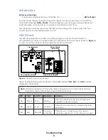
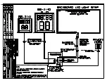
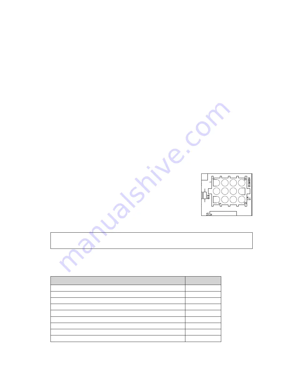
Since the same LED drivers can be used for many display
models, each driver must be set to receive the correct signal
input, or address, for the model in which it is being used.
This address is set with jumper wires in a 12-pin plug which mates
with jack
J1
on the driver (
). After replacing the driver
in the control enclosure, be sure to use an Address 1 plug in
jack
J1
. In most cases, the same plug can be reused from the
driver that was replaced; otherwise, one may be ordered from
Daktronics (part # 0A-1150-0122).
Note:
For BB-2150 and BB-2151 to display 1/10 of a second, switch 8 of DIP switch
S3
must be set to ON. Refer to
DWG-216653
for additional DIP switch settings.
Replacement Parts
The following table contains display components that may require replacement. Many of
the other display components will have attached part number labels.
Description
Part Number
Address 1 Plug
0A-1150-0122
LED Light Strip, 28.875" (BB-2140)
0A-1322-0008
LED Light Strip, 20.5" (BB-2141)
0A-1322-0009
Cable; 6-pin to 6-pin, 30'
0A-1322-0011
Horn Enclosure Assembly
0A-1322-0015
Cable Holder Assembly
0A-1322-0016
Horn Interface Card
0P-1192-0399
7" Four-Digit w/ Colon, Dual-Sided, Amber (BB-2140 & BB-2150)
0P-1322-0001
13" 7-Segment, Dual-Sided, Red (BB-2140)
0P-1322-0002
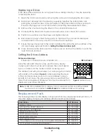
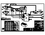
HAZARDOUS VOLTAGE
BEFORE SERVICING
DISCONNECT POWER
Driver Status
Indicators
Shot Clock Driver
Horn Interface Card
Transformers
Figure 5:
Address Jack J1
Summary of Contents for BB-2140
Page 4: ...This page intentionally left blank...
Page 18: ...This page intentionally left blank...
Page 19: ......
Page 20: ......
Page 21: ......
Page 24: ......
Page 25: ......
Page 26: ...AT EXPOSED TERMINALS HAZARDOUS VOLTAGE BEFORE SERVICING DISCONNECT POWER...
Page 27: ......
Page 28: ......
Page 31: ......
Page 32: ......
Page 33: ......
Page 34: ...This page intentionally left blank...


