


Mechanical Installation
3
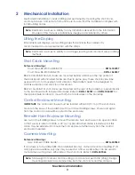
2 Mechanical Installation
Mechanical installation consists of lifting and permanently mounting the shot clocks,
control enclosure, and remote horn enclosure. Be sure that the installation complies with
local building codes.
Note:
Daktronics assumes no liability for any installation derived from the information
provided in this manual or installations designed and installed by others.
Lifting the Display
Small Daktronics displays use two lifting straps that encircle the cabinet. It is
recommended to use a spreader bar with the straps.
Note:
Daktronics assumes no liability for damages resulting from incorrect setup or lifting
methods.
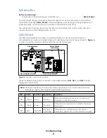
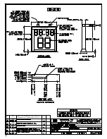
Shot Clock Mounting
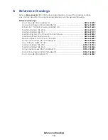
Reference Drawings:
Court View, BB-2140 and BB-2141 .....................................................................
DWG-184787
Court View, BB-2150 & BB-2151 .......................................................................
DWG-1060357
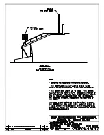
BB-2140 and BB-2150 shot clocks are mounted behind and above the top center of
the backboard with included hardware. Due to game play, these shot clocks will be
exposed to a lot of movement and vibration. The brackets need to be designed to
minimize vibration and shot clock movement.
BB-2141 and BB-2151 shot clocks are mounted on the rear of the backstop, perpendicular
to the backboard with included hardware. Refer to
DWG-184787
and
DWG-1060357
for
the approximate location to mount both shot clocks sizes on the backstop.
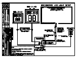
Control Enclosure Mounting
IMPORTANT:
The control enclosure must be located within 30' (9.1 m) of the shot clock.
Mount on the base of the backstop with four #10 self-drilling screws. Power and signal
from the control console will be routed to the enclosure.
Remote Horn Enclosure Mounting
Use two #10 self-drilling screws to mount the remote horn enclosure in an open location
so that sound is able to radiate. A 20' (6.1 m) pre-attached cable is included, but this
cable may be extended to mount the horn enclosure further away from the control
enclosure if needed.
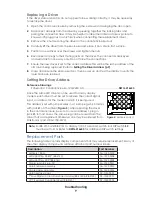
Camera Mounting
Reference Drawings:
Assy; Camera Cable Holder..............................................................................
DWG-249064
If a camera is to be added (BB-2140 and BB-2150 only), camera mounts accepting 2" (51
mm) pipe are available; only one may be used at a time. A cable tray can be used to
route camera wiring down either side of the shot clock. Refer to
DWG-249064
.
Note:
Total weight of camera and mounting arm cannot exceed 50 lb (23 kg). Design
mounting brackets to accommodate both the shot clock and the camera.
Summary of Contents for BB-2140
Page 4: ...This page intentionally left blank...
Page 18: ...This page intentionally left blank...
Page 19: ......
Page 20: ......
Page 21: ......
Page 24: ......
Page 25: ......
Page 26: ...AT EXPOSED TERMINALS HAZARDOUS VOLTAGE BEFORE SERVICING DISCONNECT POWER...
Page 27: ......
Page 28: ......
Page 31: ......
Page 32: ......
Page 33: ......
Page 34: ...This page intentionally left blank...