background image

Electrical Installation

4

3  Electrical Installation

CAUTION: Only qualified individuals should perform routing and termination to the 

display. Electrical contractors are responsible for ensuring that all electrical work meets 

or exceeds local and national codes. Daktronics engineering staff must approve all 

changes or the warranty will be void.

Installation Overview

Electrical installation involves routing power and control signal wiring through separate 

conduit or wire ways. 

Note: 

Control signal cable and some junction boxes are not provided as part of this 

system and can be purchased locally or from Daktronics.

Power

Install a grounded receptacle near the equipment so that the power cord can easily 

reach it. 
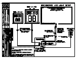
Each shot clock control enclosure comes with a 120 VAC or 240 VAC twist lock power 

plug. The power plug will need to be attached to a 120 VAC or 240 VAC power cord (by 

the customer) as follows:
• 

120 VAC wiring:

 Connect black wire to copper terminal, white wire to nickel terminal, 

and green wire to green terminal. 

• 

240 VAC wiring:

 Connect black wire to copper terminal, red wire to copper terminal, 

and green wire to green terminal. 

Grounding

All components of a display system – including but not limited to displays, control 

equipment, and connected peripheral equipment – must be electrically grounded. 

Only qualified individuals may perform electrical work, including verification of ground 

resistance. Daktronics is not responsible for improper grounding or damage incurred as a 

result of improper grounding.
Grounding methods must meet the provisions of all applicable local and national codes. 

Inspect and verify all grounding methods meet the provisions of all applicable local and 

national codes.
Proper grounding is necessary for reliable equipment operation and general electrical 

safety. Failure to properly ground the display system may void the warranty, disrupt 

operation, damage equipment, and cause bodily harm or death.

Power-On Self-Test (POST)

The display performs a self-test each time that power is turned on and the control 

console is powered off or not connected. If the control console is connected and 

powered on, the self-test does not run, and data from the control console is shown on 

the display after a few seconds. Each self-test pattern will vary depending on the model, 

the number of drivers, and types of digits. 
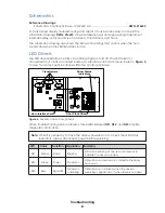
Radio Settings

If a radio receiver is installed, the radio broadcast settings (“b1”) and the channel 

settings (“C1”) will be displayed in the game clock digits during the POST. These values 

must match the settings in the control console. Refer to 

Radio Control (p�5)

 and 

Control Console (p�2)

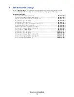
Summary of Contents for BB-2140

Page 1: ...ronics Drive Brookings SD 57006 5128 www daktronics com support 800 325 8766 TRANSPARENT SHOT CLOCKS DISPLAY MANUAL P1322 ED 15168 Rev 08 12 June 2018 Models BB 2140 BB 2150 NBA only BB 2141 BB 2151 N...

Page 2: ...o part of this book covered by the copyrights hereon may be reproduced or copied in any form or by any means graphic electronic or mechanical including photocopying taping or information storage and r...

Page 3: ...tion 4 Installation Overview 4 Power 4 Grounding 4 Power On Self Test POST 4 Radio Settings 4 Signal Connection 5 Radio Control 5 Light Strips 5 4 Troubleshooting 6 Troubleshooting Table 6 Component A...

Page 4: ...This page intentionally left blank...

Page 5: ...t drop the control equipment or allow it to get wet Specifications Label Power specifications as well as serial and model number information can be found on an ID label on the display similar to the o...

Page 6: ...sole Operation Manual ED 11976 This manual is provided on a CD with the control console and it is also available online at www daktronics com manuals Specifications The chart below details all of the...

Page 7: ...ement BB 2141 and BB 2151 shot clocks are mounted on the rear of the backstop perpendicular to the backboard with included hardware Refer to DWG 184787 and DWG 1060357 for the approximate location to...

Page 8: ...ted to displays control equipment and connected peripheral equipment must be electrically grounded Only qualified individuals may perform electrical work including verification of ground resistance Da...

Page 9: ...shown in DWG 184789 and DWG 1060264 6 Connect a signal cable from the J box to the J1 J2 or J3 jack on the back of the All Sport 5000 console Also connect the Shot Clock Start Stop Switch Daktronics p...

Page 10: ...ace console if necessary Display digits do not light but console works No wired signal from control console Check that the control enclosure is receiving 120 or 240 VAC power Check that the red DS3 LE...

Page 11: ...Verify the connector on the back of the digit circuit board is secure Bad digit or driver Exchange the digit or driver with a working one of the same part to verify the problem Replace if necessary Se...

Page 12: ...Figure 4 to view the component locations within the control enclosure HAZARDOUS VOLTAGE BEFORE SERVICING DISCONNECT POWER Driver Status Indicators Shot Clock Driver Horn Interface Card Transformers F...

Page 13: ...nce Drawings Schematic Control Enclosure 120 240V AC DWG 216653 Since the same LED drivers can be used for many display models each driver must be set to receive the correct signal input or address fo...

Page 14: ...er Transparent Shot Clock 0P 1322 0006 7 Two Digit plus Tenths Dual Sided Red BB 2151 0P 1322 0007 13 7 Segment plus Tenths Dual Sided Red BB 2150 0P 1322 0008 Transformer 16 VAC T 1066 Transformer 10...

Page 15: ...______ To participate in the Exchange Program follow these steps 1 Call Daktronics Customer Service Market Description Customer Service Number Schools including community junior colleges religious org...

Page 16: ...mage during shipment Electronic components such as printed circuit boards should be placed in an antistatic bag before boxing Daktronics does not recommend using packing peanuts when shipping 4 Enclos...

Page 17: ...sure 120 240V AC DWG 216653 Mechanical Spec BB 2140 DWG 223192 Mechanical Spec BB 2141 DWG 223193 Mechanical Spec Shot Clock Control Enclosure DWG 225832 Mechanical Spec Remote Horn DWG 235683 Electri...

Page 18: ...This page intentionally left blank...

Page 19: ......

Page 20: ......

Page 21: ......

Page 22: ...DATE REV BY DATE REV BY DATE REV BY DATE REV BY DATE REV BY DATE REV BY 06 19 AUG 15 ZSW PER EC 16838 INCREASED BASE WIDTH FROM 6 TO 8 INCREASED MTG HOLE SPACING FROM 4 875 TO 6 5...

Page 23: ...ESS WRITTEN CONSENT OF DAKTRONICS INC COPYRIGHT 2015 DAKTRONICS INC DAKTRONICS INC AV DRAWN DATE SHEET JOB NO REV TRANSPARENT SHOT CLOCKS MECHANICAL SPEC BB 2141 CBRECZI 02 MAR 05 P1322 E 10 A 1 15 CB...

Page 24: ......

Page 25: ......

Page 26: ...AT EXPOSED TERMINALS HAZARDOUS VOLTAGE BEFORE SERVICING DISCONNECT POWER...

Page 27: ......

Page 28: ......

Page 29: ...DATE REV BY 01 19 AUG 15 ZSW PER EC 16838 INCREASED BASE WIDTH FROM 6 TO 8 INCREASED MTG HOLE SPACING FROM 4 875 TO 6 5...

Page 30: ...DATE REV BY 01 19 AUG 15 ZSW PER EC 16838 INCREASED BASE WIDTH FROM 6 TO 8 INCREASED MTG HOLE SPACING FROM 4 875 TO 6 5...

Page 31: ......

Page 32: ......

Page 33: ......

Page 34: ...This page intentionally left blank...

Page 35: ...Daktronics Warranty Limitation of Liability 31 B Daktronics Warranty Limitation of Liability This section includes the Daktronics Warranty Limitation of Liability statement SL 02374...

Page 36: ...This page intentionally left blank...

Page 37: ...placement parts or Equipment will be new or serviceably used comparable in function and performance to the original part or Equipment and warranted for the remainder of the Warranty Period Purchasing...

Page 38: ...ectors employees or agents be liable for any claims asserting or based on a loss of use of the facility or equipment lost business revenues or profits loss of goodwill failure or increased cost of ope...

Reviews: