Electrical Installation
11
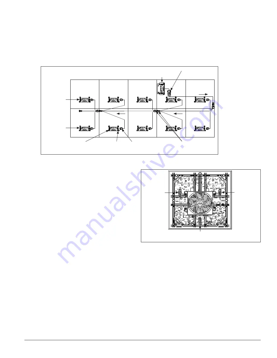
3.9 Power Redundancy
Reference Drawing;
Layout & Block Diagram
...................................................................................................
Contract Specific
Redundant power is included in the system using an N+1 power supply redundancy configuration for
protection against module power failure. If a power supply fails, the redundant power supply provides
backup power to the affected module. In regular conditions, the redundant power supply remains auxiliary.
Testing
To test the redundant power wiring
scheme/setup, with power applied to the
display, locate the last module(s) on the
redundant harnessing bus system. Refer
to the contract specific drawing for wiring
information and component placement.
Disconnect the 3-pin AC power to the power
supply on the module. Verify the LEDs or
indicator lights on the module remain lit to
ensure the module continues to work after the
AC power is disconnected.
3.10 Signal Redundancy
Reference Drawing:
Layout & Block Diagram
...................................................................................................
Contract Specific
There are two different levels of signal redundancy: module redundancy, which is part of the standard
design, and full-data redundancy.
Standard Module Redundancy
Module redundancy provides a primary and redundant SATA connection throughout the entire display to
protect the system from signal failure. If a module in the middle of a signal chain fails, the redundant signal
path takes over and limits the signal failure to that single module.
N+1 redundant
power supply
Redundant power
supply 4-pin DC out
Redundant path
Redundant path
Power supply
on module
Power supply
on module
3-Pin AC
input
Redundant path
2-Pin 12V DC output
harness to module
power supply
Redundant harness
interconnect point
2-Pin 12V
DC input
Figure 15:
Power Redundancy
Signal Port B
Module
power jack
Signal Port A
Figure 16:
Module Rear with Jacks
Summary of Contents for DAKT-0204-02
Page 10: ...6 Cabinet Installation...
Page 28: ...24 Maintenance Troubleshooting...
Page 32: ......
Page 34: ......
Page 36: ......
Page 41: ......
Page 61: ......


