background image


Section 1: 

Introduction 

This manual explains the installation, maintenance, and troubleshooting of a Daktronics 
Galaxy

®

 AE-3010 Indoor Tri-color LED display. For questions regarding the safety, 

installation, operation, or service of this system, please refer to the telephone numbers listed 
on the cover page of this manual. 
 
This manual is divided into eight sections: Introduction, Mechanical Installation, Electrical 
Installation, Maintenance and Troubleshooting, Appendix A, Appendix B, Appendix C and 
Appendix D. 


Introduction 

covers the basic information needed to make the most of the rest 

of this manual. Take time to read the entire introduction as it defines terms and 
explains concepts used throughout the manual. 


Mechanical Installation 

provides general guidance on sign mounting. 


Electrical Installation 

gives general guidance on terminating power and signal 

cable at the sign. 


Maintenance and Troubleshooting 

addresses such things as removing basic 

sign components, troubleshooting the sign, performing general maintenance, 
and exchanging sign components. 


Appendix A

 includes the drawings referenced in this manual. 


Appendix B 

contains general information about the signal converters. 


Appendix C 

provides general information about the optional temperature 

sensor. 


Appendix D

 provides information on the configuration of the serial server. 

 
Daktronics identifies manuals by an ED number located on the cover page of each manual. 
For example, this manual would be referred to as 

ED-11169

 
Listed below are a number of drawing types commonly used by Daktronics, along with the 
information that each is likely to provide. This manual might not contain all these drawings. 


System Riser Diagrams:

 Overall system layout from control computer to sign, 

power, and phase requirements. 


Shop Drawings:

 Fan locations, mounting information, power and signal 

entrance points, and access method (front and rear). 


Schematics: 

Power and signal wiring for various components. 


Component Placement Diagrams:

 Locations of critical internal sign 

components, such as power supply assemblies, controller boards, thermostats, 
and light detectors. 


Figure 1


illustrates the Daktronics drawing label. The drawing number is located in the lower-

right corner of the drawing. Listing the last set of digits and the letter preceding them 
identifies drawings in the manual. In the example below, the drawing would be referred to as 

Drawing B-206146

. Reference drawings are inserted after the section that references them. 


Figure 1: Drawing Label 

Introduction 
 

1-1

Summary of Contents for Galaxy AE-3010

Page 1: ... Series AE 3010 7 62 mm Display Manual ED11169 Rev 6 19 March 2009 331 32 nd PO Box 5128 Brookings SD 57006 Tel 605 697 4034 or 877 605 1113 Fax 605 697 4444 Hwww daktronics comH email helpdesk daktronics com ...

Page 2: ...y for errors or omissions No part of this book covered by the copyrights hereon may be reproduced or copied in any form or by any means graphic electronic or mechanical including photocopying taping or information storage and retrieval systems without written permission of the publisher Galaxy and Venus are registered trademarks of Daktronics Inc All others are trademarks of their respective compa...

Page 3: ... of the page blank on back Section heading pages always start on a new page they never start on the back of another page 3 Drawings included in this manual are located within Appendix A 4 Insert ED 14413 in Appendix B 5 Insert ED 15176 in Appendix D 6 Insert SL 02374 in Appendix E 7 Use a blue window cover and a blue back 8 Punch all pages window cover and back cover along the left edge and bind w...

Page 4: ......

Page 5: ...ectors in the Sign 3 1 3 2 Control Cable Categories 3 2 Cable Types 3 2 Installing an RJ11 Connector 3 3 3 3 Power 3 3 3 4 Grounding 3 4 3 5 Signal Termination from Computer to Display 3 4 RS232 3 4 RS422 3 5 Modem 3 7 TCP IP or LAN System 3 7 3 6 Signal Connection Between Two or More Displays 3 8 3 7 Initial Operation 3 9 Section 4 Maintenance and Troubleshooting 4 1 4 1 Maintenance and Troublesh...

Page 6: ...turn Programs 4 10 4 9 Daktronics Warranty and Limitation of Liability 4 11 Appendix A Reference Drawings 1 Appendix B Signal Converter 1 Appendix C Optional Temperature Sensor 1 Appendix D Serial Server Configuration 1 Appendix E Daktronics Warranty and Limitation of Liability SL 02374 1 ...

Page 7: ...onnectors 3 3 Figure 17 Wire with Outer Jacket Stripped 3 3 Figure 18 Power Cord Connection 3 4 Figure 19 RS232 System Layout 3 4 Figure 20 RS232 Input Connection 3 5 Figure 21 RS422 System Layout 3 5 Figure 22 RS422 Signal Converter Connections 3 6 Figure 23 Modem System Layout 3 7 Figure 24 TCP IP Ethernet System Layout 3 8 Figure 25 RS422 Interconnection 3 8 Figure 26 Signal Summary using RS422...

Page 8: ...List of Figures iv Figure 37 Temperature Sensor Connection and Interconnection 1 Figure 38 Signal Connection from Sensor to Display 2 ...

Page 9: ...on about the signal converters Appendix C provides general information about the optional temperature sensor Appendix D provides information on the configuration of the serial server Daktronics identifies manuals by an ED number located on the cover page of each manual For example this manual would be referred to as ED 11169 Listed below are a number of drawing types commonly used by Daktronics al...

Page 10: ...ite label that lists the part number The component part number is in the following format 0P _ _ _ _ _ _ _ _ component or 0A _ _ _ _ _ _ _ _ multi component assembly Following the Replacement Parts List is the Daktronics Exchange and Return and Repair Programs in Section 4 8 Refer to these instructions if any sign component needs replacement or repair 1 1 Safety Precautions Important Safeguards 1 ...

Page 11: ...equired for signal installation is standard six 6 conductor modular telephone wire and a tool to install the connector Tools required for mounting the display depend on the location and size of the display For some installations it may be possible to purchase pre terminated telephone cables for use with the displays There are four 4 network systems available RS232 RS422 modem and TCP IP Ethernet R...

Page 12: ... to Section 4 for the summaries of how signal and power are routed through the displays Galaxy displays are graphic indoor LED displays which are available in tri color red green and amber characters Daktronics offers Galaxy displays with a 7 62 center to center spacing with characters in six 6 different lengths The Galaxy model numbers are described as follows AE 3010 RRxCCC 7 62 TRI AE 3010 Indo...

Page 13: ... responsible for the switching and intensity levels of the LEDs Figure 3 16x32 Pixel Module Front and Rear View Power Supply Converts AC line voltage from the load center to low DC voltage for one or more module driver boards Galaxy Daktronics trademarked name for LED monochrome or tri colored matrix signs Network Consists of multiple signs connected to each other Up to 240 Venus 1500 controlled d...

Page 14: ...communications through an RJ11 jack Signal Converter Daktronics supplied unit that converts the data from RS232 to RS422 or RS232 to fiber optic signal The signal converter is connected to the control PC via a straight though serial cable The RS232 to RS422 signal converter is shown in Figure 4 1 5 Daktronics Nomenclature To fully understand some Daktronics drawings such as schematics it is necess...

Page 15: ...n be used when requesting replacement parts from Daktronics Customer Service Take note of the following part number formats 0P _ _ _ _ _ _ _ _ denotes an individual circuit board such as a driver board 0A _ _ _ _ _ _ _ _ represents an assembly such as a circuit board and the plate or bracket to which it is mounted A collection of circuit boards working as a single unit may also carry an assembly l...

Page 16: ......

Page 17: ...ion contained in this section is general information only and may or may not be appropriate for your particular installation A qualified individual must make all decisions regarding the mounting of this sign Read both the mechanical and electrical installation sections of this manual before beginning any installation procedures 2 2 Support Structure Design Daktronics recommends either a wall mount...

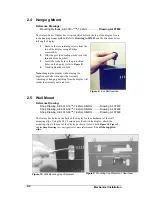
Page 18: ... display without using the supplied eyebolts will negate the warranty Attaching or hanging anything from the display will render the warranty null and void 2 5 Wall Mount Reference Drawing Shop Drawing AE 3010 16 7 62mm SB RG Drawing A 107618 Shop Drawing AE 3010 32 7 62mm SB RG Drawing A 107636 Shop Drawing AE 3010 48 7 62mm SB RG Drawing A 107639 The Galaxy has holes on the back of the display f...

Page 19: ...play model to determine the location of the bracket with respect to the display Be sure the bracket is mounted to sufficiently support the weight of the display Have all mountings inspected by a qualified structural engineer 2 Set the display on the wall mounted bracket The bracket fits onto the wall mounting clips as shown in the reference drawings ...

Page 20: ......

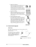
Page 21: ...resents some common connectors encountered during sign installation and maintenance 1 Ribbon Cable Connectors Figure 11 illustrates a typical ribbon cable connector To disconnect the ribbon cable push the plastic clips on the sides of the jack inward Before replacing a ribbon cable connector spray it with DeoxIT contact cleaner to remove any foreign matter that may cause signal problems In additio...

Page 22: ...nectors RJ11 and RJ45 connectors are similar to the telephone and network connectors found in homes and businesses cables In order to remove this plug from the jack depress the small clip on the underside of the plug Before replacing an RJ connector spray it with DeoxIT contact cleaner to remove any foreign matter that may cause signal problems In addition apply a generous amount of CalLube protec...

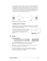
Page 23: ...r TH 1033 performs two separate steps Figure 17 Wire with Outer Jacket Stripped First use the crimping tool to strip the outer insulation from the inner wires This does not result in bare wires since only the gray outer jacket is removed After correct stripping the wire will appear as shown in Figure 17 3 3 Power Reference Drawings Shop Drawing AE 3010 16 7 62mm SBRG Drawing A 107618 Shop Drawing ...

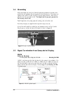
Page 24: ...The socket outlet should be installed near the equipment and be easily accessible Plug the power cord into the back of the display as shown in Figure 18 Figure 18 Power Cord Connection 3 5 Signal Termination from Computer to Display RS232 Reference Drawings V1500 System Riser Diagram RS 232 Drawing A 91388 A RS232 system connects the first sign directly to the computer via an adapter The adapter h...

Page 25: ... the RS232 IN jack Pin Number Function 1 RTS OUT P 2 RESET OUT P 3 TX OUT N 4 GND 5 RX IN N 6 DCD IN P RS422 Reference Drawings V1500 System Riser Diagram RS422 Drawing A 91387 An RS422 system connects the first sign through a signal converter near the computer A serial cable W 1249 connects to the signal converter and an RJ11 flipped cable will connect from there to the display Refer to Figure 21...

Page 26: ...ctions Signal Converter to Display Connection Using Flipped Cable Signal Converter J2 J3 RS422 OUT RS422 IN Jack on the Display Pin 1 GND Pin 1 N C Pin 2 TX N Pin 2 D1OUT P Pin 3 TX P Pin 3 D1OUT N Pin 4 RX N Pin 4 D1IN P Pin 5 RX P Pin 5 D1IN N Pin 6 GND Pin 6 N C Note The table of the pine outs of the signal converter and the RS422 In at the display illustrate that the pinouts to both are the sa...

Page 27: ...port on the computer to the input on the modem then connect a phone line from the modem to the wall jack Plug in the power pack to the external modem 2 Connect an RJ11 phone line from the wall jack to the input on the back of the display 3 The display requires a dedicated phone line Pin out of the Modem In Jack Pin Number Function Pin 1 N C Pin 2 N C Pin 3 TIP P Pin 4 Ring P Pin 5 N C Pin 6 N C TC...

Page 28: ... 25 RS422 Interconnection The signal connection between displays is the same for all types of systems Refer to the System Riser Diagram for your system for the connection method When wiring from display to display the RJ11 cable between displays will always be flipped See Section 3 2 for descriptions and methods for making flipped cables The best method of wiring the displays together is to start ...

Page 29: ... last display will have nothing in the output jack 3 7 Initial Operation Each time power is applied to the display the display will run through an initialization in which it will display the following 1 Output Test DDDs 2 Product Name Galaxy 3 Display Size Row x Column 4 Firmware Number ED10134 5 Firmware Revision Rev X XX 6 COM1 Configuration C1 V15 RTD 7 COM2 Configuration C2 None 8 Line Frequen...

Page 30: ......

Page 31: ...is Galaxy display in a safe working order Troubleshooting lists some possible display malfunctions and provides a number of possible causes for that malfunction Replacement Parts List includes the description and part number of display components that may need replacing during the life of this display Exchange and Repair and Return Programs explain Daktronics component return policy 4 2 Signal Sum...

Page 32: ... fuse It is then distributed to the transformer and the power supplies mounted to the back sheet of the display 3 The controller board receives about 10 VAC from the transformer 4 The power supplies are set to 5 3 VDC For assistance with the wiring to the power supplies see the Schematics Power supplies are preset Contact Daktronics Customer Service for the proper settings 4 4 Service and Diagnost...

Page 33: ...nel to the cabinet one quarter turn counter clockwise The screws are designed to remain in the LED module flanges but release from the cabinet 4 Gently tilt the LED module panel downward from the body of the display The panel will be supported in a horizontal position by lanyards DO NOT use the module panel to support additional weight Refer to Figure 29 Figure 27 Removing the Screws from the Face...

Page 34: ...tdriver remove the module screws from the rear of the panel 6 Gently pull the failed module from the panel Reverse the previous steps to attach a new module Figure 30 Disconnecting Power from LED Module Figure 31 LED Module Ribbon Cable Removal Power Supply Replacement Note Disconnect power from the display before removing a power supply Figure 32 Loosening Power Supply Screws Power to the LED mod...

Page 35: ... proper wiring configuration Accessing and Replacing the Controller Board The display controller is mounted to the back sheet of the cabinet in the lower left corner The controller receives interprets and activates the information from the computer to the appropriate LEDs on the display The controller board includes three LEDs 1 DS1 should be on whenever power is applied to the board 2 DS2 should ...

Page 36: ...set using DIP switches located on a PC board known as the MDC The MDC is the circuit card mounted on the left end of the controller board Locate the DIP switches on the MDC They should be on the bottom end of the card Refer to Figure 35 for a picture of the DIP switches When replacing a controller board be sure to set the DIP switches to the same address configuration as the defective controller T...

Page 37: ...that is not working Move Replace the second module that isn t working Replace controller Entire display is garbled Power down and power back up to watch bootup sequence Check power to controller board Replace the controller board A single line is distorted Check Replace ribbon cable Check for bent pins on module jacks Replace the first module on the left side of the display of the bad line Replace...

Page 38: ... Auto dimming in Venus 1500 software Check light detector cable Replace light detector Replace controller board 4 6 Initial Operation Information Each time the display is powered up the display will run through an initialization in which it will display the following 1 Output Test DDD s 2 Product Name Galaxy 3 Display Size Row x Column 4 Firmware Number ED10134 5 Firmware Revision Rev X XX 6 COM1 ...

Page 39: ...25M 6 W 1249 Adapter DB9M to DB25F A 1603 PC Adapter DB9 to RJ11 0A 1115 0042 PC Adapter DB25 to RJ11 0A 1115 0044 Serial Server RS232 mode 0A 1146 0063 Adapter DB25M to RJ11F RS232 Serial Server 0A 1115 0045 Serial Server RS422 mode 0A 1146 0064 Adapter DB25M to RJ11F RS422 Serial Server 0A 1146 0062 Cable RJ45 10 ft 4 pair twisted Black W 1383 25 RJ11 6 cond cable W 1265 100 RJ11 6 cond cable 0A...

Page 40: ... part if it does not solve the problem For most equipment you will be invoiced for the replacement part at the time it is shipped This invoice is due when you receive it Daktronics reserves the right to refuse equipment that has been damaged due to acts of nature or causes other than normal wear and tear If the defective equipment is not shipped to Daktronics within 30 working days from the invoic...

Page 41: ...k 1 877 605 1113 toll free or 1 605 697 4034 Customer Service Fax 1 605 697 4444 E mail helpdesk daktronics com 4 9 Daktronics Warranty and Limitation of Liability The Daktronics Warranty and Limitation of Liability is located in Appendix X The Warranty is independent of Extended Service Agreements and is the authority in matters of service repair and display operation ...

Page 42: ......

Page 43: ... A 91387 System Riser Diagram RS232 Drawing A 91388 Shop Drawing AE 3010 16 7 62mm SB RG Drawing A 107618 Shop Drawing AE 3010 32 7 62mm SB RG Drawing A 107636 Shop Drawing AE 3010 48 7 62mm SB RG Drawing A 107639 Mounting Methods AE 3010 7 62mm Drawing A 107655 System Riser Diagram TCP IP Network Drawing A 231373 Schematic AE 3010 32 2 1 Drawing B 102485 Schematic AE 3010 48 2 1 Drawing B 102706 ...

Page 44: ......

Page 45: ......

Page 46: ......

Page 47: ......

Page 48: ......

Page 49: ......

Page 50: ......

Page 51: ......

Page 52: ......

Page 53: ......

Page 54: ......

Page 55: ......

Page 56: ...Appendix B Signal Converter Appendix B Signal Converter B 1 ...

Page 57: ...5128 Brookings SD 57006 Tel 605 697 4034 or 877 605 1113 Fax 605 697 4444 www daktronics com e mail helpdesk daktronics com Daktronics RS 232 422 Signal Converter Installation and Testing Manual ED 14413 Rev 2 18 March 2005 ...

Page 58: ...er assumes no responsibility for errors or omissions No part of this book covered by the copyrights hereon may be reproduced or copied in any form or by any means graphic electronic or mechanical including photocopying taping or information storage and retrieval systems without written permission of the publisher All trademarks are the property of their respective companies ...

Page 59: ...st Outdoor Displays 1 3 1 2 RS422 Loop Back Test Indoor Outdoor Displays 1 4 1 3 Loop Back test with Fiber 1 5 1 4 Conducting the Venus 1500 Software Test 1 6 Section 2 Electrical and Signal 2 1 2 1 Electrical Ratings 2 1 2 2 Power Disconnect 2 1 2 3 Parts Listing 2 1 Section 3 Mounting Instructions 3 1 Section 4 Enviromental Ratings 4 1 ...

Page 60: ......

Page 61: ...o open computer COM port On Steady 1 Serial port or serial cable is bad 2 Computer COM port is in sleep mode 1 Try another port or replace serial cable 2 Communicate with display OFF Steady Normal state Signal Converter is not transmitting data TX Brief Flicker SC is transmitting data ON Steady 1 Field cabling between Signal Converter and display is bad 2 Is connected to display output jack or ter...

Page 62: ...1 PIN OPERATION 1 GND 2 TX N out 3 TX P out 4 RX N in 5 RX P in 6 GND J1 25 Pin DB F PIN OPERATION 2 TX P out 3 RX P in 7 GND Fiber Signal Converter The following tables give the jack pin outs for a fiber signal converter Figure 2 RS232 Fiber Signal Converter Signal Converters and Loop Back Testing for Direct Connections 1 2 JACK OPERATION J2 TX1 out J3 RX1 in J4 TX2 out J5 RX2 in J1 25 Pin DB F P...

Page 63: ...ted into it J2 and J3 J4 and J5 Pin 5 TX N to Pin 3 RX N OR Pin 2 RX P to Pin 4 TX P Pin 4 TX P to Pin 2 RX P Pin 3 RX N to Pin 5 TX N Figure 4 Jumpers at Surge Board When the wires are connected perform the loop back test using the Venus 1500 software as described in Section1 4 This test can also be done at the signal termination enclosure on the surge board assembly as shown in Figure 4 or on so...

Page 64: ...use of a flipped reversed or straight cable can be determined visually Use the figures below as a guide or use the Network Cable Tester box for assistance Figure 5 Flipped Cable Reversed Figure 6 Straight Cable 1 Plug one end of the flipped cable into the output from the computer or signal converter Signal Converters and Loop Back Testing for Direct Connections 1 4 2 Plug one end of the flipped ca...

Page 65: ...e the fiberboard as shown in Figure 9 and label the fiber ends connected to the board 3 Remove the ends from the board that are in jacks J5 and J4 4 Connect the ends into the fiber splice Daktronics part P 1197 as shown in Figure 10 5 When the fibers are connected perform the loop back test using the Venus 1500 software as described in Section 1 4 6 For AF 3010 and X 1000 displays only the cable t...

Page 66: ...1 Open Venus 1500 Administrator 2 Click Network Configuration and open the direct network by clicking on the in front of Direct Network 3 Right click the network you want to test Signal Converters and Loop Back Testing for Direct Connections 1 6 ...

Page 67: ...nfigured as a serial port If the Transmit LED flickered this was not the problem b A communication problem exists The fiber or the ends on the fiber are bad or The wire or the terminations are bad c There was a problem conducting the test The serial cable to the signal converter is bad or not plugged in The signal converter is not plugged in 8 If the words It appears as if this port has a modem at...

Page 68: ......

Page 69: ...WG or larger telecommunication line cord This product is to be used with UL and c UL listed computers 2 1 Electrical Ratings The Signal Converter is rated for 120 VAC of power in and a maximum draw of 39mA 2 2 Power Disconnect The power cord serves as the disconnect device and the socket outlet must be installed near the equipment and must be easily accessible 2 3 Parts Listing The following parts...

Page 70: ......

Page 71: ...table mounted Do not mount the signal converter from the ceiling or the underside of a table To mount the signal converter refer to drawing B 200645 Secure the signal converter using a screw though the mounting holes at the the back of the enclosure Do not fully tighten the screws Figure 11 Signal Converter Enclosure Mounting Instructions 3 1 ...

Page 72: ......

Page 73: ...Enviromental Ratings 4 1 Section 4 Enviromental Ratings The signal converter is made for indoor operations and is rated for indoor use only ...

Page 74: ......

Page 75: ...es extra stability and accuracy to the sensor because of the added shading usually obtained on a northern exposure There should be at least one foot between the bottom of the eave and the top of the temperature sensor housing for accurate readings as seen in Figure 36 Due to the nature of the signal cable used to send the temperature information the maximum distance between the temperature sensor ...

Page 76: ...play The connections are pinned one to one as shown in Figure 38 and the provided table Figure 38 Signal Connection from Sensor to Display Terminations from Display to Temperature Sensor Display Cable Wires Temperature Sensor Pin 1 Green Temp RX P Pin 1 Pin 2 White Temp RX N Pin 2 Pin 3 Red Temp 5V Pin 3 Pin 4 Black Temp GND Pin 4 Pin 5 Bare N A C 2 ...

Page 77: ...Appendix D Serial Server Configuration D 1 Appendix D Serial Server Configuration ...

Page 78: ......

Page 79: ...Daktronics Warranty and Limitation of Liability SL 02374 E 1 Appendix E Daktronics Warranty and Limitation of Liability SL 02374 ...

Reviews: