Display Troubleshooting
19
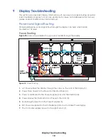
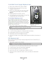
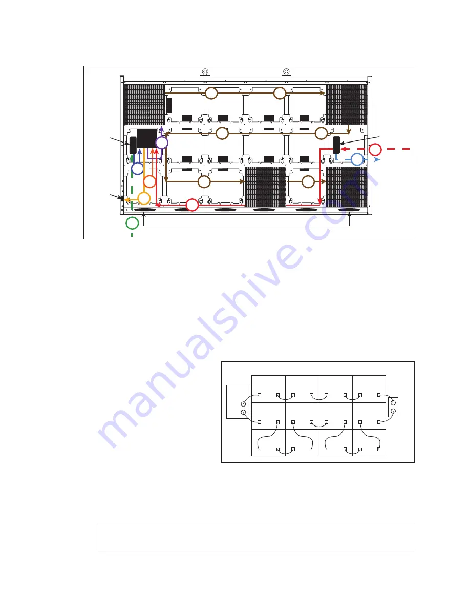
Signal Routing
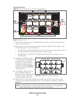
shows how signal is routed through the display.
1�
Signal enters the display from the external signal enclosure through the signal input
quick-connect jacks (1).
2�
Signal travels from the J32 signal input jack through an Ethernet Cat5e cable to the
J32 Ethernet jack on the controller (2a).
•
The J33 auxiliary input jack and jack J31, for optional external temperature sensor,
connect to breakout harness to jack J36 on the controller.
•
The light sensor is connected to the breakout harness to the J36 jack on the
Controller (2b).
3�
In single-face displays, signal
travels from the Controller SATA
A jack to SATA A on the first
Module (3a) and travels from
module to module via SATA
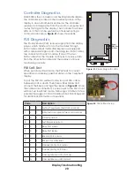
cables (3b). Refer to
Signal returns to the Controller
SATA B jack (3c).
4�
In 2V displays, signal from the
primary display face RJ45
Quick Connect travels from the
Primary Out jack to the mirror
face (4) to the Mirror In jack.
5�
Signal returns from the mirror display via the Mirror Out jack to the Primary In jack
on the primary display and finally returns to the Controller SATA B jack (5). Refer to
.
Note:
One-high displays must be located less than 20' apart to accommodate
signal redundancy between primary and mirror displays.
Input
Quick
Connect
Light
Detector
DMP
Thermostat
RJ45
Quick
Connect
Fans
PS
PS
PS
PS
PS
PS
PS
PS
1
2a
3b
3b
3b
3b
3b
3b
5
5
2b
3c
3a
4
Figure 19:
Signal Routing
RJ 45
QC
DMP
Primary Face - Even Columns
Figure 20:
Module-to-Module Signal Routing

