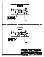
12 VDC Horn Installation
2
Horn Plate Assembly Installation
Reference Drawings:
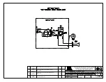
Plate Assy: Outdoor SCBD 12VDC Horn- AS5K ................................................
DWG-128944
DWG-128944
shows the components of the horn plate assembly.
1�
Open the horn entrance panel as described in
2�
On the interior of the back panel of scoreboard, drill two 5/32" holes 4" apart (these
holes may have been pre-drilled at the factory). The enclosure is to be attached to
the inside of the scoreboard and accessible when the entrance panel is opened.
Note:
Be careful not to damage any internal components when drilling!
3�
Attach the enclosure to the scoreboard using the #10 tapping screws provided.
4�
Attach the plate assembly to the enclosure using #10 tapping screws provided.
5�
Attach the cover to the enclosure using the #10 tapping screws provided.
Trumpet Horn Installation
Preparation
Reference Drawings:
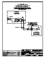
Horn Assembly .....................................................................................................
DWG-320004
1�
Insert bushings into the appropriate 3/8" holes in the mounting angle.
2�
Thread the two gray wires from the horn through the top of the mounting angle.
3�
Attach the horn to the mounting angle using the #10 hardware provided.
4�
Thread the two gray wires through the 3/8" hole in the rear of the mounting angle.
Installation
Reference Drawings:
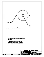
Template, Hole Drilling, Trumpet Horn ................................................................
DWG-83502
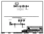
F.Assy: 12V DC Horn Mounting- Outdoor LED SCBD .....................................
DWG-3067687
1�
Locate the horn entrance panel as described in
. Remove the 2"
knockout on this panel. If a knockout has not been provided, use
DWG-83502
as a
guide to drill one 3/8" hole and two 7/32" holes in the panel.
Note:
Be careful not to damage any internal components when drilling!
2�
Thread the two gray wires from the horn through the knockout (or 3/8" hole) in the
scoreboard access panel.
3�
Place horn/angle bracket assembly over the 2" knockout and 7/32" holes in the front
panel of the scoreboard and attach using #10 hardware provided.
4�
Using the wiring nuts provided, connect one gray wire from the horn to the black wire
from the plate assembly. Connect the other gray wire to the red wire.
5�
Route the 2-pin horn plate plug labeled
P3
to jack
J3
on the horn interface card, per
DWG-3067687
. If the harness does not reach, connect the 2-pin to 2-pin extension
cable between the horn plate and the horn interface card as needed.
6�
Close and secure the horn entrance panel.
7�
To test the horn, power on the scoreboard and control console, and press
HORN
.
Summary of Contents for P1192
Page 4: ...This page intentionally left blank...
Page 12: ...This page intentionally left blank...
Page 14: ...This page intentionally left blank...
Page 15: ......
Page 20: ......
Page 22: ...This page intentionally left blank...
Page 24: ......
Page 26: ......


