


120 VAC Trumpet Horn Installation
5
Horn Installation
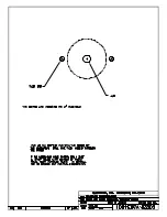
Reference Drawings:
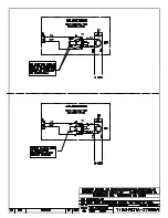
Template, Hole Drilling, Trumpet Horn ................................................................
DWG-83502
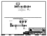
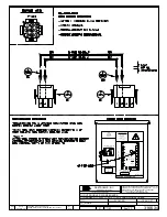
120V AC Horn Mounting, Outdoor Sports ......................................................
DWG-1055044
Horn Mtg Instructions; 120V, TI-2003, Gyrus Driver .........................................
DWG-3054691
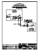
Horn Card Installation; Gyrus Driver ................................................................
DWG-3067686
1�
Locate the horn entrance panel as described in
. Remove the 2"
knockout on this panel. If the knockout has not been provided, use
DWG-83502
as a
guide to drill one 2" hole in the panel.
Note:
Be careful not to damage any internal components when drilling!
2�
Remove the trumpet from the horn body by unscrewing it.
3�
Mount the bracket to the scoreboard frame using #10 hardware provided, and
connect the horn harness to the horn wires with included wire nuts. Refer to
DWG-
1055044
. For the TI-2003 only, refer instead to
DWG-3054691
.
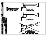
When replacing a horn:
a�
Use 1/4" bolts, nuts, and lock washers provided to attach the horn body to the
mounting bracket so that the horn is on the same side as the short flange (the
horn should be pointing downward).
b�
Be sure to mount the horn to the bracket so that the wires are facing the bottom
of the cabinet to prevent water from running along them.
c�
Attach the copper ground lug to the bottom-right corner of the mounting
bracket using the bolt and serrated washer and nut provided, and connect the
green wire from the horn to the ground lug (
does not apply to the TI-2003
).
4�
Route the 2-pin horn plug labeled
P3
to jack
J3
on the horn interface card, per
DWG-
3067686
. If the harness does not reach, connect the 2-pin to 2-pin extension cable
between the horn and the horn interface card as needed.
5�
Close the access panel and screw the trumpet back onto the horn body.
6�
To test the horn, power on the scoreboard and control console, and press
HORN
.
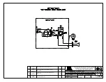
Schematics
Reference Drawings:
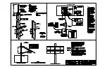
Schematic: 120VAC Trumpet Horn ...................................................................
DWG-132173
Summary of Contents for P1192
Page 4: ...This page intentionally left blank...
Page 12: ...This page intentionally left blank...
Page 14: ...This page intentionally left blank...
Page 15: ......
Page 20: ......
Page 22: ...This page intentionally left blank...
Page 24: ......
Page 26: ......


