


DH
THE CONCEPTS EXPRESSED AND DETAILS SHOWN ON THIS DRAWING
ARE CONFIDENTIAL AND PROPRIETARY. DO NOT REPRODUCE BY
ANY MEANS WITHOUT THE EXPRESS WRITTEN CONSENT OF
DAKTRONICS, INC. OR ITS WHOLLY OWNED SUBSIDIARIES.
COPYRIGHT 2019 DAKTRONICS, INC. (USA)
THIRD ANGLE PROJECTION
REV
TITLE:
PROJECT:
INCHES [MILLIMETERS]
DESIGN:
SCALE:
DIM UNITS:
DATE:
SHEET
DO NOT SCALE DRAWING
FUNC - TYPE - SIZE
DRAWN:
-
JOB NO.
-
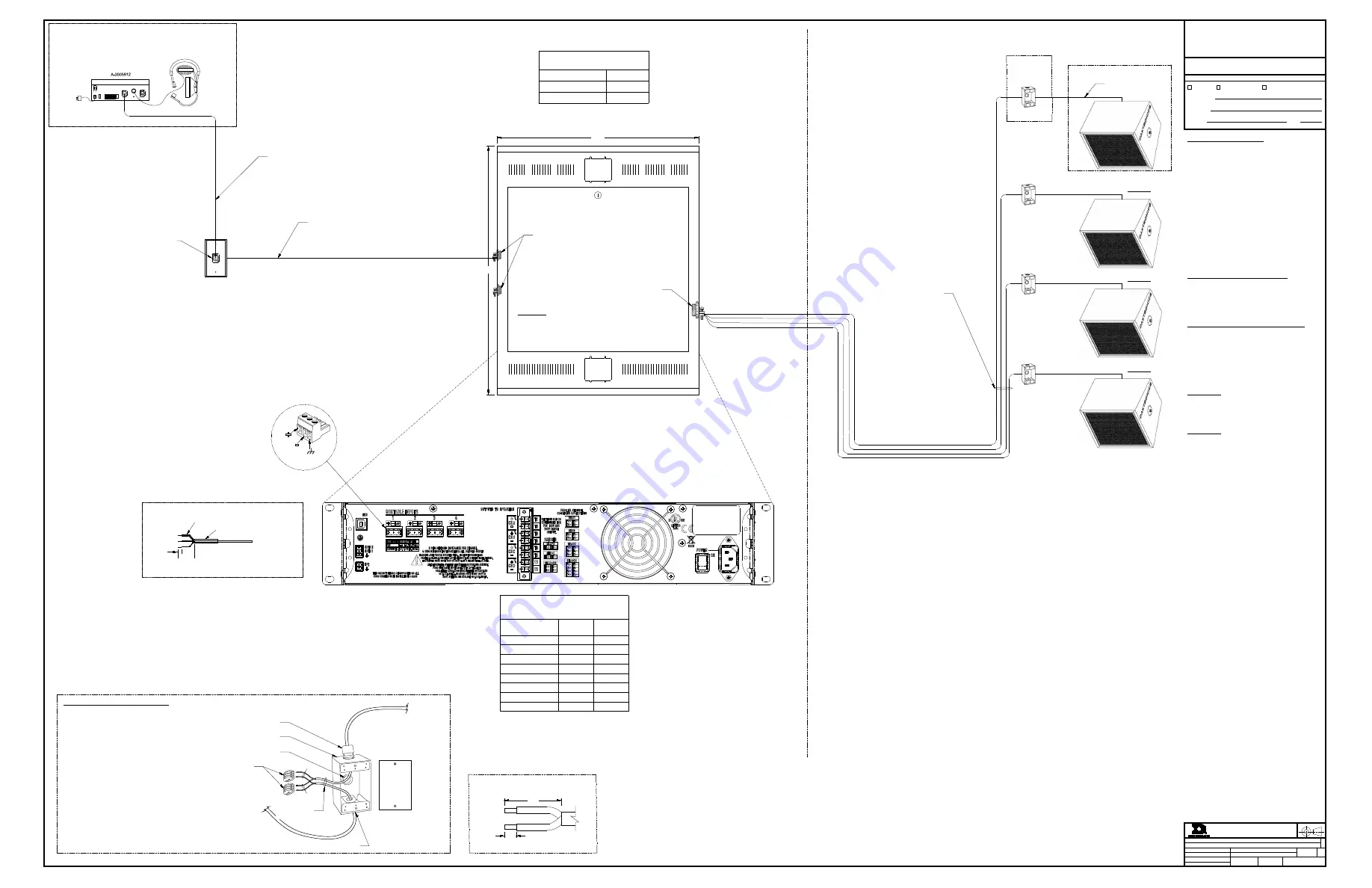
SPORTSOUND SYSTEMS
RISER; SS-200, ELECTRICAL, PERMANENT SYSTEM
CBRANDT
8 OCT 19
P1756
F 01 D
NONE
CBRANDT
4306294
00
SPORTSOUND
OUTDOOR AUDIO SYSTEM
SS-200
APPROVED
APPROVED AS NOTED
APPROVED AS NOTED & RESUBMIT
COMPANY:
SIGNED:
TITLE:
DATE:
SUBMITTAL APPROVAL
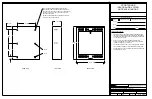
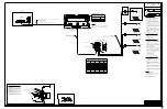
PERMANENT MOUNTED AMPLIFIER RACK
0A-1756-0075
LAYOUT VIEW
24.5"
30.2"
(PAR1)
RACK IS SURFACE MOUNTED TO WALL
RACK DEPTH = 7.9"
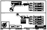
AMPLIFIER REAR VIEW
SIGNAL INPUT PLATE
EC-1244
LAYOUT VIEW
CONNECT TO SSR CONTROL
SYSTEM OUTPUT
XLR PINOUT:
PIN1 = SHLD
PIN2 = + (RED)
PIN3 = - (BLK)
AMPLIFIER SIGNAL INPUT
CONNECTOR DETAIL
BLK
RED
SHLD
W-1615, AUDIO SIGNAL CABLE, FIELD INSTALLED,
FROM EC-1244 TO ROUTABLE INPUT 1 ON AMPLIFIER
PT-1024 (SMALL GREEN HEATSHRINK)
PT-1009 (3/16" BLACK HEATSHRINK)
1"
0.25"
SIGNAL CABLE TERMINATION DETAIL
SHLD
BLK
RED
EC-1008 @2
EC-1131
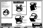
SPEAKER (SPK#) NOTES: 0A-1756-0074
1. SPEAKER ENCLOSURE PROVIDED BY DAKTRONICS AND
INSTALLED BY INSTALL SUBCONTRACTOR.
SPEAKER WEIGHT WITHOUT MOUNT = 55 LBS ea.
2. 30 FOOT 12AWG, W-1745, SPEAKER CABLE WHIP
PRE-TERMINATED TO SPEAKER ENCLOSURE FOR FIELD
TERMINATION TO LOCAL JUNCTION BOX (LJB#).
3. 250 FOOT COIL OF W-1745 PROVIDED WITH EACH SPEAKER
FOR LJB# TO SJB1 CONNECTION. CUT TO LENGTH AFTER
INSTALLATION.
4. IF SPEAKER IS MOUNTED WITHIN 30 FEET OF PERMANENT
AMP RACK (PAR1), WIRE CAN BE ROUTED DIRECTLY TO
PAR1, LOCAL JUNCTION BOX (LJB#) MAY NOT BE NEEDED.
5. MOUNTING YOKE PROVIDED WITH EACH SPEAKER.
SECONDARY BRACKETS WILL BE PROVIDED BASED ON SITE
SPECIFIC NEEDS; POLE VS ROOF, WALL, OR SOFFIT
MOUNTING.
SEE DWG-04306807 FOR POLE MOUNTING DETAILS.
SEE DWG-04561669 FOR ROOF, WALL, OR SOFFIT MOUNTING
DETAILS.
6. SYSTEM MAY CONTAIN ONE (1) TO FOUR (4) SPEAKERS
LOCAL JUNCTION BOX (LJB#) NOTES: 0A-1756-0081
1. 1-GANG, LOCAL JUNCTION BOX (LJB#) PROVIDED WITH EACH
SPEAKER.
2. MOUNTED WITHIN RANGE OF PROVIDED
SPEAKER WHIP (30 FEET).
3. SEE LJB# INSTALLATION DETAILS
PERMANENT AMPLIFIER RACK (PAR1) NOTES: 0A-1756-0075
1. PERMANENT AMPLIFIER RACK PROVIDED BY DAKTRONICS.
PERMANENT AMP RACK WEIGHT = 65 LBS.
2. DO NOT ALLOW AMPLIFIER RACK TO GET WET . MOUNT
INDOORS ONLY.
3. ANY CONTROL SYSTEM (SSR-###) CONNECTED TO
ROUTBALE INPUT 1 OR ROUTABLE INPUT 2 WILL BE SENT TO
ALL FOUR SPEAKER OUTPUTS. SSR-AM IS SHOWN ON THIS
DRAWING, BUT ANY SSR CONTROL SYSTEM CAN BE USED
WITH SS200 SYSTEM.
W-1745 DETAILS;
1 PAIR, 12 AWG, SPEAKER CABLE
OUTER DIAMETER = 0.352"
COLOR = BLACK
RATED FOR DIRECT BURIAL AND OUTDOOR USE, CONDUIT
NOT NECESSARY, IF CONDUIT IS USED SIZE ACCORDING TO
SITE CONDITIONS
W-1615 DETAILS;
1 PAIR, 22AWG WITH SHIELD, AUDIO SIGNAL CABLE
OUTER DIAMETER = 0.170"
COLOR = BLACK
CONDUIT TO BE USED AND SIZED ACCORDINGLY TO SITE
CONDITIONS
SEE DD4310070 FOR SYSTEM MANUAL
SEE DWG-04275565 FOR SYSTEM SCHEMATIC
SPEAKER CABLE TERMINATION DETAIL; W-1745
0.33"
(+) RED
(-) BLK
2.0"
AMPLIFIER TO SPEAKER
WIRING CHART
AMPLIFIER PIN T# SPEAKER
WIRE
SPK WIRE
COLOR
(CH A+) - T1
SPK 1 +
RED
(CH A-) - T2
SPK 1 -
BLACK
(CH B+) - T3
SPK 2 +
RED
(CH B-) - T4
SPK 2 -
BLACK
(CH C+) - T5
SPK 3 +
RED
(CH C-) - T6
SPK 3 -
BLACK
(CH D+) - T7
SPK 4 +
RED
(CH D-) - T8
SPK 4 -
BLACK
MAXIMUM WATTS
AMPERES PER LINE
SYSTEM VOLTAGE
NUMBER OF POLES
WIRES + GND
TOTAL POWER REQUIREMENTS:
CIRCUIT 1
120
2
1
1300W
10.8A
POWER NOTE:
-3' LOCKING POWER CORD INCLUDED WITH AMPLIFIER RACK
-DEDICATED 20A 120VAC CIRCUIT MOUNTED IN RACK
RECOMMENDED WITH DUPLEX OUTLET
-P-1127 (N5-15) PLUG PROVIDED IF POWER CORD NEEDS TO BE
ROUTED OUTSIDE OF RACK, USE EC-1008 FOR CABLE STRAIN RELIEF
30' SPEAKER WHIP INCLUDED
W/ SPEAKER, TYP.
W-1745, 1 PAIR, 12AWG, SPEAKER WIRE, TYP.
FIELD INSTALLED
MAX LENGTH = 250 FT PER SPEAKER (PROVIDED)
SPEAKER #1 (SPK1)
(OPTIONAL)
SPEAKER #4
(SPK4)
SPEAKER ASSEMBLY;
0A-1756-0074
(OPTIONAL)
SPEAKER #3
(SPK3)
(LJB1)
(LJB2)
(LJB3)
(LJB4)
LOCAL JUNCTION
BOX;
0A-1756-0081
SEE (LJB#) DETIALS
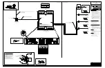
XLR CABLE PROVIDED WITH ONE OF THE FOLLOWING CONTROL SYSTEM OPTIONS;
SSR-AM (12 FOOT CABLE)
SSR-100 (25 FOOT CABLE)
SSR-200 (25 FOOT CABLE)
REAR VIEW
ANNOUNCER'S
MIXER
PHONES
OUT
MIX
OUTPUT
MIC
INPUT
SETUP
SELECTOR
120 VAC
CIRCUIT
A/C
12VAC
600mA
CHASSIS
GND
LFT
OUTPUT
PAD
ON
OFF
A-2382
ANNOUNCER'S
HEADSET
A-2382
SSR-AM
ANNOUNCER'S MIXER KIT
0A-1756-0047
TO SPEAKER
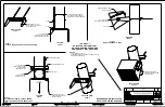
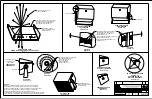
LOCAL JUNCTION BOX (LJB#) INSTALLATION DETAILS
-ATTACH SUPPLIED METAL MOUNTING TABS TO LJB#
(EC-1166) WHERE NECESSARY, OPPOSITE CORNERS
OF BOX PREFERRED.
-USE SUPPLIED 0.5" PLASTIC PLUG TO SEAL REAR
THREADED CONDUIT CONNECTION, USE SILICONE IN
PLUG THREADS.
-INSTALL EC-1176 IN TOP AND BOTTOM OF BOX
-ROUTE SPEAKER WHIP AND FIELD INSTALLED
SPEAKER CABLE INTO JUNCTION BOX AS SHOWN.
-FOLLOW SPEAKER CABLE TERMINATION DETAIL FOR
CABLE/WIRE STRIP LENGTHS
-CONNECT WIRES AS SHOWN USING E-1184
-INSTALL BLANK FACEPLATE WITH GASKET (EC-1081)
-BOX MOUNTING HARDWARE PROVIDED BY OTHERS
TO SJB1
EC-1176
E-1184
WIRE NUTS
EC-1176
0.5" CABLE STRAIN RELIEF
RED
BLK
W-1745
SPEAKER CABLE
EC-1166
1-GANG STEEL OUTDOOR ELECTRICAL BOX
EC-1081
1-GANG
COVER
(OPTIONAL)
SPEAKER #2
(SPK2)
OUTDOOR MOUNTED EQUIPMENT
INDOOR MOUNTED EQUIPMENT
*USE SUPPLIED PLUG TO SEAL HOLE*
Summary of Contents for P1756
Page 4: ...This page intentionally left blank ...
Page 18: ...This page intentionally left blank ...
Page 20: ...This page intentionally left blank ...
Page 28: ...This page intentionally left blank ...
Page 30: ...This page intentionally left blank ...


