


12
Controls & Timing Functions
7.
Shot Clock.
In this program, the display shows the tens and ones of seconds on the two
center digits. The display counts down to 0:00 from a configured time and sounds the
horn. The operator can configure the time from 0 to 99 seconds. In this mode, a <
START
>
will start the display counting, a <
STOP
> will stop the display from counting.
The <
RESET
> switch will operate in one of two ways depending on which input was
pressed last. If <
START
> was pressed last, when <
RESET
> is pressed, the display will
reset to the configured time. When <
RESET
> is released, the display will start counting.
If <
STOP
> was pressed last, when <
RESET
> is pressed, the display will reset to the
configured time. When <
RESET
> is released, the display will stay at the configured time
and wait for a <
START
> to begin counting. This mode automatically configures the
SIGNAL IN port on the PC-2001 to receive the signal from an All Sport
®
console or an
OmniSport
®
2000 timer for use as a portable shot clock display (such as for water polo).
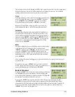
8.
12-Hour Time of Day (TOD).
This program displays the time of day using a 12-hour
clock. The current time can be set via the switches on the side of the display or the JC-100.
9.
24-Hour Time of Day.
This program displays time of day using the 24-hour military
clock. The current time can be set via the switches on the side of the display or the JC-100.
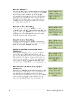
10.
Start Reaction Timer, Normally Open (Daktronics).
With a relay take-off platform, this
program shows the difference in time between the start signal and the last platform
signal. The results show as a negative if the swimmer leaves the relay take-off platform
before the start signal.
11.
Relay Exchange Timer, Normally Open (Daktronics).
This program shows the exchange
time between the touchpad signal and the last relay take-off platform signal. Results
show as a negative if the swimmer leaves the relay take-off platform before the previous
swimmer touches the touchpad.
Note:
An All Sport
®
control console or an OmniSport
®
timing console can be connected to the
PC-2001 as an input device. The PC-2001 will then display the information received from the
console.
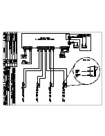
Drawing A-192024
in
Appendix A
contains information on connecting multiple PC-
2001 displays in series using these consoles, the JC-100 and the switches on the side.
JC-100 Console Operation
Connect the 4-pin power/signal cable from the JC-100 Judges Console to the AUX. PORT on
the side of the PC-2001. The keypad insert number needed for operation is LL-2584
(
Drawing
A-191855
in
Appendix A
).
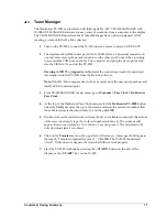
When the PC-2001 is turned on and the JC-100 is connected, press <
MENU
> on the control
console to view the available options. Use the up and down arrows to scroll through these
options, or press the number located next to the option.
Press <
ENTER
> when the desired action is on the screen.
Press the <
MENU
> button at any time to exit.
MENU-[CURR MODE]
1-SETTINGS
Summary of Contents for PC-2001
Page 2: ......
Page 4: ......
Page 6: ......
Page 10: ......
Page 24: ......
Page 30: ......
Page 32: ......
Page 33: ......
Page 34: ...JC 100 SWIM STOP REST LL 2584 REV 01 CIRCUIT PACE CLOCK...
Page 35: ......
Page 36: ......
Page 37: ...Daktronics Warranty and Limitation of Liability 27...
Page 38: ......


