background image


20


Display Maintenance 

  Replacing the Digit/Driver Printed Circuit Board 

1.


To access the digit/driver PCB, remove the 10 outer screws to separate the front and 
back panels of the display. 

2.


Disconnect all power and signal connections from the PCB by squeezing together the 
locking tabs and pulling the connector free.  

3.


Remove the 8 nuts securing the PCB to the front panel of the display. Take note of the 
orientation of the PCB for future reference. 

4.


Carefully remove the PCB from the studs and spacers on the front panel. Use an even 
force to prevent any damage that might result from bending the LEDs or connector 
pins on the board. 

5.


Position the new PCB over the studs, making sure there is a spacer between the front 
panel and circuit board.


6.


Tighten the 8 nuts. 

7.


Reconnect all power/signal connectors. 
 

Note:

 These are keyed connectors and will attach in one way only. Do not attempt to 

force the connections. 
 

8.


Close and secure the back panel, then power on and test the display. 


  Replacing Batteries 

CAUTION:

 Do not allow any metal object, including jewelry, to contact the battery terminal – 

a short-circuit on a battery can produce very high current, causing equipment damage or 
severe burns! 
 
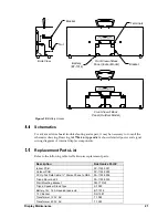
To remove and replace a battery, refer to 

Figure 10

 and follow these steps: 


1.


Remove the 10 outer screws to separate the front and back panels of the display. 

2.


Disconnect the power leads from the terminals. 

3.


Remove the 4 nuts securing the battery bracket. 

4.


Remove and replace the battery. 

5.


Reconnect the power leads to the terminals of the new battery exactly as follows:  

RED to the POSITIVE terminal, BLACK to the NEGATIVE terminal

6.


Tighten the 4 nuts to secure the battery bracket. 

7.


Close and secure the back panel. 

 
Do not throw old battery in trash. The battery contains lead and should be recycled. 

Summary of Contents for PC-2001

Page 1: ...System Display Manual ED 13737 Rev 3 23 September 2010 201 Daktronics Drive PO Box 5128 Brookings SD 57006 5128 Tel 1 800 DAKTRONICS 1 800 325 8766 Fax 605 697 4700 Web www daktronics com Email helpd...

Page 2: ......

Page 3: ...al including photocopying taping or information storage and retrieval systems without written permission of the publisher All Sport and OmniSport are trademarks of Daktronics Inc Other trademarks used...

Page 4: ......

Page 5: ...ction 14 Mode 4 Relay Reaction Normally Closed Omega 14 Mode 5 Workout 14 Mode 6 Game Clock 15 Mode 7 Shot Clock 16 Mode 8 12 Hour Time of Day 16 Mode 9 24 Hour Time of Day 16 Mode 10 Start Reaction N...

Page 6: ......

Page 7: ...efore servicing power supplies to avoid electrical shock Power supplies run on high voltage and may cause physical injury if touched while powered Do not modify the scoreboard structure or attach any...

Page 8: ...s Part Type Part Number Individual circuit board 0P XXXX XXXX Assembly a collection of circuit boards 0A XXXX XXXX Wire or cable W XXXX Fuse F XXXX Transformer T XXXX Metal part M XXX Fabricated metal...

Page 9: ...trol capabilities Manufactured in two models the outdoor version of the timing display is designated as PC 2001 11 while the indoor unit is designated PC 2001 13 The timing display is powered by 12 V...

Page 10: ......

Page 11: ...s Note Do not attempt to permanently suspend the PC 2001 by its carrying handle Also do not permanently mount outdoor displays or leave in wet weather Before beginning installation place the bracket a...

Page 12: ...HS 1315 2 Remove the two knockouts from the bottom by pushing them in 3 Attach the tripod adapter plate using the rubber bumpers and screws O ring Bumper Tripod bracket HS 1306 Screw Tripod adapter p...

Page 13: ...To recharge the system simply plug the power cable into a grounded power receptacle The recharging unit will not overcharge the batteries Indicator lights on the side control panel show when the unit...

Page 14: ...Auto Off has occurred turn the power switch off wait a few minutes and then turn it back on In the case of a low battery be sure to plug the display into a charger before continuing use Signal The PC...

Page 15: ...9 System Setup System setup information for each of the programs is shown in Figure 7 This chart is also printed on a vinyl quick reference decal on the rear of the display case Figure 7 PC 2001 Progr...

Page 16: ...Relay Take Off Platform 11 Relay Exchange Timer w Daktronics Relay Take Off Platform Note Refer to Section 4 3 for more information about each program To modify the preset time for programs 1 5 6 and...

Page 17: ...take off platform before the previous swimmer touches the touchpad If a touchpad is not plugged into the PC 2001 but a platform is the STOP button can emulate a touchpad being touched and starts timi...

Page 18: ...de of the display or the JC 100 10 Start Reaction Timer Normally Open Daktronics With a relay take off platform this program shows the difference in time between the start signal and the last platform...

Page 19: ...U and then press ENTER Scroll down to 3 HORN and press ENTER Press ENTER again to allow the selection of the Horn option Use the up and down arrows to select between the AUTO default and MANUAL and th...

Page 20: ...rly leave Press the RESET key to start the program over Mode 5 Workout To edit a workout press MENU followed by ENTER on the 1 EDIT WORKOUT option Select the step number to change or add and press ENT...

Page 21: ...NTER to confirm the whole workout is to be cleared After entering all the desired timing options press START to begin the workout Horn The workout mode has a few different horn options than other mode...

Page 22: ...de 10 Start Reaction Normally Open Daktronics When the PC 2001 is plugged into a relay take off platform the START key starts timing from the time the key is pressed to the time the swimmer leaves the...

Page 23: ...Hy Tek computer does not have a serial port the user must purchase and install a USB to serial adaptor 3 From TEAM MANAGER s main menu go to Workouts Pace Clock Daktronics Pace Clock 4 At the top of t...

Page 24: ......

Page 25: ...connectors horn and other components All switches power systems and input output terminations are connected to the PCB As shown in Figure 9 the PCB is attached to the front panel of the display Refer...

Page 26: ...connectors Note These are keyed connectors and will attach in one way only Do not attempt to force the connections 8 Close and secure the back panel then power on and test the display Replacing Batte...

Page 27: ...2 AH sealed lead acid BT 1014 12 V Buzzer DS 1487 Transformer 120 V AC T 1085 Transformer 230 V AC T 1093 Nut Back half of outdoor display Back half of indoor display Terminals Bracket Battery BT 101...

Page 28: ...junior colleges religious organizations municipal clubs and community centers 877 605 1115 Universities and professional sporting events live events for auditoriums and arenas 866 343 6018 2 When the...

Page 29: ...air of the part 3 Package and pad the item carefully to prevent damage during shipment Electronic components such as printed circuit boards should be placed in an antistatic bag before boxing Daktroni...

Page 30: ......

Page 31: ...rawings 25 Schematic PC 2001 and TI 2022 Drawing A 177466 Insert LL 2584 JC 100 Pace Clock Drawing A 191855 Riser Diagram PC 2001 Portable Install Drawing B 192024 Riser Diagram PC 2001 PC 2002 Drawin...

Page 32: ......

Page 33: ......

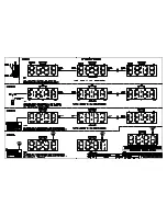
Page 34: ...JC 100 SWIM STOP REST LL 2584 REV 01 CIRCUIT PACE CLOCK...

Page 35: ......

Page 36: ......

Page 37: ...Daktronics Warranty and Limitation of Liability 27...

Page 38: ......

Page 39: ...r any unapproved return Purchaser shall pay any upgraded or expedited transportation charges D Any replacement parts or Equipment will be new or serviceably used comparable in function and performance...

Page 40: ...be liable to Purchaser or any other party for loss damage or injury of any kind or nature arising out of or in connection with this Warranty in excess of the purchase price of the Equipment actually d...

Reviews: