


Display Maintenance
21
Schematics
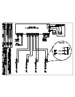
For advanced scoreboard troubleshooting and repair, it may be necessary to consult the
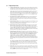
schematic drawing. Drawing
A-177466
in
Appendix A
shows detailed power and signal
wiring diagrams of internal display components.
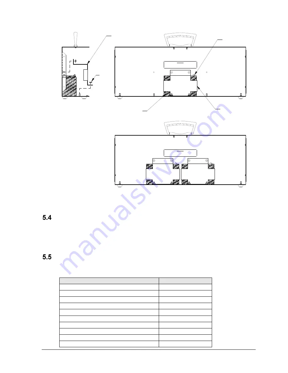
Replacement Parts List
Refer to the following table for Daktronics replacement parts:
Description
Daktronics Part #
Indoor PCB
0P-1153-0001
Outdoor PCB
0P-1153-0003
20' Hy-Tek Data Cable; ¼" Stereo Phone to DB9
0A-1153-0036
Tripod Mounting Kit
0A-1153-0325
Wall Mounting Bracket
0M-173125
Tripod, Speaker Stand Type
A-1580
Battery, 12V 7.2 AH sealed lead-acid
BT-1014
12 V Buzzer
DS-1487
Transformer, 120 V AC
T-1085
Transformer, 230 V AC
T-1093
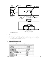
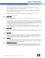
Nut
Back half of outdoor display
Back half of indoor display
Terminals
Bracket
Battery
(BT-1014)
Bracket
Front View
Side View
Front View
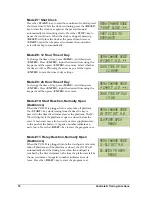
IMPORTANT
CONNECT RED WIRE TO POSITIVE (+) TERMINAL.
CONNECT BLACK WIRE TO NEGATIVE (-) TERMINAL.
IF CONNECTED OTHERWISE, THE DISPLAY WILL NOT WORK PROPERLY AND MAY
DAMAGE COMPONENTS OR CAUSE INJURY.
IMPORTANT
CONNECT RED WIRE TO POSITIVE (+) TERMINAL.
CONNECT BLACK WIRE TO NEGATIVE (-) TERMINAL.
IF CONNECTED OTHERWISE, THE DISPLAY WILL NOT WORK PROPERLY AND MAY
DAMAGE COMPONENTS OR CAUSE INJURY.
Figure 10:
Battery Access
Side View
Front View of Back
Panel (Outdoor Model)
Front View of Back
Panel (Indoor Model)
Battery
(BT-1014)
Bracket
Terminals
Bracket
Nut
Summary of Contents for PC-2001
Page 2: ......
Page 4: ......
Page 6: ......
Page 10: ......
Page 24: ......
Page 30: ......
Page 32: ......
Page 33: ......
Page 34: ...JC 100 SWIM STOP REST LL 2584 REV 01 CIRCUIT PACE CLOCK...
Page 35: ......
Page 36: ......
Page 37: ...Daktronics Warranty and Limitation of Liability 27...
Page 38: ......


