Electrical Installation
7
Displays With Internal Power Termination
To terminate single-phase power
to the internal power termination
panel, complete these steps:
1�
Open the display as explained
and locate the power
termination panel.
2�
Route the cable through
conduit to the rear of the
display. Use the
3
/
4
" knockout
for access, being careful not to
damage internal components.
3�
Connect the neutral wire to the
neutral lug and the live wires to
the Line 1 and Line 2 lugs.
4�
The ground wire connects to
the grounding bus bar. Refer to
CB1
15
CB2
15
CB3
15
CB4
15
Z1 Top
Z2 Bottom
LINE
LOAD
Z3 Top
Z4 Bottom
LINE
LOAD
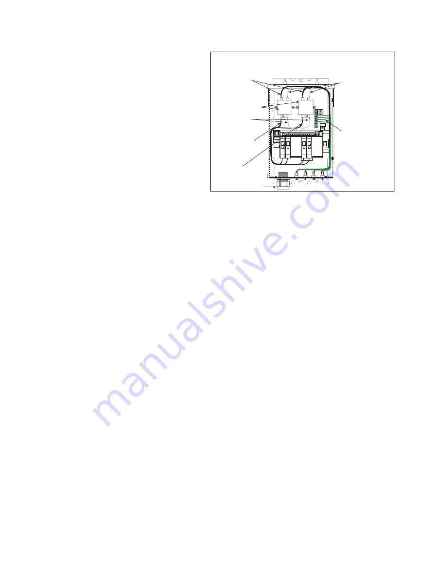
Four Breaker Connections
• White Neutral Wiring
(Z1 Load to Pin 1 of J41)
• White Neutral Wiring
(Z2 Load to Pin 1 of J42)
• White Neutral Wiring
(Z3 Load to Pin 1 of J43)
• White Neutral Wiring
(Z4 Load to Pin 1 of J44)
Green Ground Wiring
(Ground Bar to Pin 3 of J41)
(Ground Bar to Pin 3 of J42)
(Ground Bar to Pin 3 of J43)
(Ground Bar to Pin 3 of J44)
• Black Line Wiring
(Z1 Load to Pin 2 of J41)
• Black Line Wiring
(Z2 Load to Pin 2 of J42)
• Black Line Wiring
(Z3 Load to Pin 2 of J43)
• Black Line Wiring
(Z4 Load to Pin 2 of J44)
Mount Z1 On Top of Z2
and Z3 On Top of Z4
White Neutral Wiring
(Terminal Neutral Block
to Z1, Z2, Z3, and Z4 Line)
Black Line Wiring
(CB1 to Z1 Line
and CB2 to Z2 Line)
Black Line Wiring
(CB3 to Z3 Line
and CB4 to Z4 Line)
LINE 2
NEUT.
LINE 1
Strain Relief
Figure 5:
Single-phase Four Breaker Domestic Panel


