background image

Daktronics Exchange and Repair & Return Programs

28

12  Daktronics Exchange and Repair & Return 

Programs

Daktronics Exchange and Repair & Return Programs

To serve customers’ repair and maintenance needs, Daktronics offers both an Exchange 

Program and a Repair & Return Program.

Exchange Program

Daktronics offers a unique Exchange Program as a quick service for replacing key parts 

in need of repair. If a part requires repair or replacement, Daktronics sends the customer 

a replacement, and the customer sends the defective part to Daktronics. This decreases 

display downtime.

Before Contacting Daktronics

Identify these important part numbers:
Display Serial Number:

Display Model Number:

Contract Number: 

Date Installed:

Location of Display (Mile Marker Number):

Daktronics Customer ID Number: 
To participate in the Exchange Program, follow these steps:

1� 

Call Daktronics Customer Service:
•  United States & Canada: 1-800-DAK-TRON (325-8766)
•  Outside the U.S. & Canada: +1-605-275-1040

2� 

When the new exchange part is received, mail the old part to Daktronics. 

If the replacement part fixes the problem, send in the problem part which is being 

replaced.

a� 

Package the old part in the same shipping materials in which the replacement 

part arrived.

b� 

Fill out and attach the enclosed UPS shipping document.

c� 

Ship the part to Daktronics.

3� 

A charge will be made for the replacement part immediately, unless a qualifying 

service agreement is in place. In most circumstances, the replacement part will be 

invoiced at the time it is shipped. 

If the failed part or replacement part is not returned to Daktronics within 3 weeks of 

the ship date, Daktronics will assume that the customer is purchasing the replacement 

part and will send an invoice for the value of the new sale part. If the part or parts are 

returned within 2 weeks of the second invoice date, Daktronics will credit the customer 

for the second invoice. 
If after 2 weeks Daktronics has still not received the parts back, the customer must pay 

the second invoice and will not be credited for the return of the failed part. Daktronics 

reserves the right to refuse parts that have been damaged due to acts of nature or 

causes other than normal wear and tear.

Summary of Contents for SMALL MATRIX GALAXY GS6 Series

Page 1: ...201 Daktronics Drive Brookings SD 57006 5128 www daktronics com support 800 325 8766 SMALL MATRIX GALAXY GS6 SERIES INSTALLATION AND OPERATION MANUAL P1817 DD3125362 Rev 13 22 April 2022 ...

Page 2: ...limits for a Class A digital device pursuant to part 15 of the FCC Rules These limits are designed to provide reasonable protection against harmful interference when the equipment is operated in a commercial environment This equipment generates uses and can radiate radio frequency energy and if not installed and used in accordance with the instruction manual may cause harmful interference to radio...

Page 3: ...gured For DHCP Default 10 Network Requirements 10 Installation Start up Steps 10 Display Configured For Static IP Address 10 Network Requirements 11 Configuration Steps Using IP Address 11 Configuration Using DisplayFind To Discover The Display 12 Download DisplayFind 12 Launch DisplayFind 12 Connect To A Display 13 Connect A Display To A Static IP Network 14 Display Currently Configured for DHCP ...

Page 4: ... Currently Configured for DHCP Default 35 Network Requirements 35 Installation Start up Steps 35 Display Configured For Static IP Address 35 Network Requirements 35 Configuration Steps Using IP Address 35 Installation Start up Steps 35 Display Configured For Static IP Address 35 Network Requirements 35 Configuration Steps Using IP Address 36 Configuration Using DisplayFind To Discover The Display ...

Page 5: ...ontrol system Refer to Daktronics Warranty and Limitation of Liability p 33 at the end of this manual for the full Daktronics Warranty and Limitation of Liability Contact Information For assistance before during or after display installation please contact Daktronics Technical Support 1 800 DAK TRON 325 8766 Model Number Guide Galaxy Small Matrix GS6 model numbers are defined as follows GS6 RxC M ...

Page 6: ...er is available at sign structure refer to the Shop Drawing for display power requirements The display cabinet has no holes accidental or intentional that will allow water to enter the display All display modules are fully latched into the display cabinet Structure Requirements Support structure design depends on mounting method installation height display size and weight Because every installatio...

Page 7: ... listed on the Shop Drawing Use all lift eyes when lifting the display Do not open the DMP enclosure Do not drill holes into the display unless noted Do not block display ventilation system Do not use the lift eyes for display mounting Display Installation 1 Carefully remove shipping crate 2 Attach a crane or lift truck to the lift eyes on the display s top Note Use a spreader beam to ensure prope...

Page 8: ...the display submit detailed drawings for the proposed modifications to the Daktronics engineering staff for evaluation and approval or the warranty will be void Improper installation could result in serious damage to the equipment and could be hazardous to personnel Size conductors of circuits that deliver power to the display according to national and local electrical codes so the power distribut...

Page 9: ...through conduit following local code specifications 3 Terminate display power either to the J box or internally at the power termination panel 4 Connect the grounding conductor to the grounding lug on the rear of the display 5 Route signal cable to the signal termination enclosure Ground the enclosure to an isolated earth ground connector when required 6 Route signal into the enclosure through con...

Page 10: ...en terminated to the J box on displays However larger displays require power to be terminated internally in the Power Termination Panel Displays With an External Power Termination J box To terminate hot neutral and ground wires at the J box follow these steps 1 Route the power cable through conduit to the rear of the display and into the power termination J box the J box contains 3 4 threaded cond...

Page 11: ...NE LOAD Z3 Top Z4 Bottom LINE LOAD Four Breaker Connections White Neutral Wiring Z1 Load to Pin 1 of J41 White Neutral Wiring Z2 Load to Pin 1 of J42 White Neutral Wiring Z3 Load to Pin 1 of J43 White Neutral Wiring Z4 Load to Pin 1 of J44 Green Ground Wiring Ground Bar to Pin 3 of J41 Ground Bar to Pin 3 of J42 Ground Bar to Pin 3 of J43 Ground Bar to Pin 3 of J44 Black Line Wiring Z1 Load to Pin...

Page 12: ... Communication Quick Guide Wireless Ethernet Bridge DD1685027 DD1417586 Ethernet DD1417609 DD1417573 Fiber Ethernet DD1417611 DD1417581 Primary Mirror Display Interconnections If this display is a two sided primary mirror display two quick connect cables are provided to connect the signal between the two faces Refer to Figure 6 for an example 1 Connect a cable from the Signal Out jack on primary f...

Page 13: ...and State MAC Address Configuration Port Status Port Management Port Used to Access Configuration Description Start Up Checklist Confirm power is correctly connected to the display Confirm there is sufficient power according to display requirements Confirm a main disconnect is installed Confirm the display is grounded per local and national codes Confirm that all communication equipment is install...

Page 14: ...play configuration by the customer s network and eliminates manual configuration of the player When the display is connected to a network that supports DHCP a default DHCP name similar to DMP8 xx xxxx or DMP5 xx xxxx where xxxx represents a unique identifier for the display is shown in the display boot sequence Requirements For Communication Through A Network The display must be allowed to establi...

Page 15: ... same IP address range as the display and same subnet 4 Manually enter display IP address in web browser followed by 85 for example http 169 254 13 87 85 to identify the correct connection port 5 Enter Dak as the username and DakPassword as the password in the Windows Security window 6 Click OK to connect to the display refer to the help file for additional information about the configuration util...

Page 16: ...e click the DisplayFind icon on your desktop Each item listed at the top of the DisplayFind utility should have a green check mark Refer to the explanations below for what each item means If an item has a red X next to it click it for additional information or to access the download The Current User Is An Administrative User On This Computer The user must have administrative rights to install Silv...

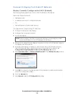
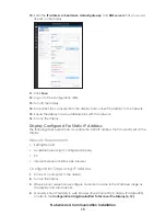
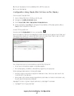
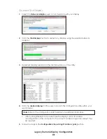
Page 17: ...e listed in the bottom window of the utility 4 Click the desired display VIP5 xx xxx to launch the configuration utility within your web browser Note Refer to the configuration utility help file for additional information After running DisplayFind to determine th e display s static IP address reconfiguration of the computer to the same IP address range and subnet may be required 5 Follow the steps...

Page 18: ... should time out searching for a DHCP server and fall back to auto IP addresses of 169 25x x x 4 Observe boot sequence reconfigure computer to same in the IP address range as the display and same subnet 5 Manually enter display IP address in web browser followed by 85 for example http 169 254 13 87 85 to identify the correct connection port Refer to the Configuration Using DisplayFind To Discover ...

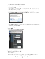
Page 19: ...red For Static IP Address The following steps explain how to update the static IP address that is currently set on the display Network Requirements Existing Network Available network port configured properly PC Internet Explorer or Firefox web browser Configuration Steps Using IP Address 1 Connect a computer to the display 2 Turn on the display 3 Observe boot sequence reconfigure computer to same ...

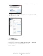
Page 20: ... file for additional information about the configuration utility 7 Click the Network tile 8 Change the IP address settings to new values 9 Click the Save button 10 Click Upload Configuration 11 Turn off display 12 Disconnect the computer from the display and connect display to the network 13 Ensure the display has an established link with the network 14 Turn on the display ...

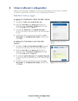
Page 21: ...s required only for the first time login to VCS 4 Update the account information fields in the User Information and Additional Information sections and click Save Logging In Customer Local Hosted Server 1 Navigate to https ComputerName 44300 entering the actual computer name for ComputerName 2 Enter the user name and password provided by Daktronics into the Email and Password text boxes and click ...

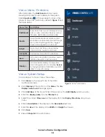
Page 22: ...rtisers Users Lists current user profiles and allows users to update passwords or add new users Displays Lists all available displays and provides basic management tools including Devices for linking DMP 8000s DMP 5000s and VIP 5X60s to a specific display Venus System Setup To add displays to Venus follow these steps 1 Click Menu on the top left side of the initial dashboard screen 2 Click Display...

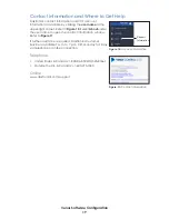
Page 23: ... under the user name to open the contact information window Refer to Figure 11 If further assistance is required Daktronics Customer Service is available 7 a m to 7 p m CST Monday to Friday via telephone or online connection Telephone United States Canada 1 800 DAK TRON 325 8766 Outside the U S Canada 1 605 275 1040 Online www daktronics com support Support Information Figure 10 Account Informatio...

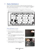
Page 24: ... of the display with a 1 8 hex head wrench A component layout is shown in Figure 12 3 Locate the latch fastener near the top center of the module refer to Figure 13 Turn the wrench a quarter turn counter clockwise 4 Gently tip the top of the module outward slightly Then lift the module upward to disengage the tabs at the bottom of the module from the slots on the display s face sheet 5 Disconnect ...

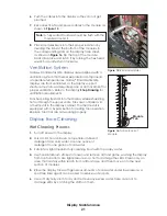
Page 25: ...to the display while exhausting hot air through the upper vents Fans are controlled via a thermostat in the display cabinet The thermostat is equipped with a bypass button for testing fan operation Replace fans that are not working properly Display Face Cleaning Wet Cleaning Process 1 Turn off power to the display 2 Mix a mild non abrasive non petroleum based detergent and cold water Use one ounce...

Page 26: ... dry soft terry cloth towel horizontally across each row of LEDs Make four passes per row of LEDs before moving to the next row of LEDs Work from top to bottom safely within reach from a lift or a stage Take care not to damage LEDs or the plastic louvers by catching the cloth on them ...

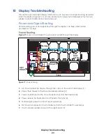
Page 27: ...ows an example of how power is routed through the display 1 AC Power enters the display through the J box on the rear of the display 1 2 Power then travels to the Power Termination Panel 2 3 Power is distributed to the Power Supplies 3a and Thermostat 3b 4 Power leaves the thermostat and travels to the fans 4 5 Modules get power from the Power Supplies 5 6 DC Power is supplied to the Controller 6 ...

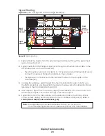
Page 28: ...Controller SATA A jack to SATA A on the first Module 3a and travels from module to module via SATA cables 3b finally returning to the Controller SATA B jack 3c 4 In 2V displays signal from the primary display face RJ45 Quick Connect travels from the Primary Out jack to the mirror face 4 to the Mirror In jack 5 Signal returns from the mirror display via the Mirror Out jack to the Primary In jack on...

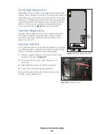
Page 29: ...ule Self Test If a module is blank but has power supplied to it perform a module self test to diagnose a module or signal cable failure To perform a self test follow these steps 1 Attach a signal cable to Port A and Port B on the module as shown in Figure 20 2 Disconnect the power to the module for 10 seconds 3 Reconnect the power to start the self test 4 Verify the module is running a self test R...

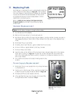
Page 30: ...splay s face sheet 4 Disconnect the power cable 5 Carefully disconnect the two signal cables from the module 6 Connect the two signal cables to the new module 7 Connect the power cable 8 Insert the tabs at the bottom of the module in the corresponding slots on the display face sheet as shown in Figure 15 Tip the top of the module back into place and latch it by turning the hex head wrench a quarte...

Page 31: ...e opened Replace the entire enclosure 1 Remove the modules in front of the controller Note Do not allow the modules to hang by their cables 2 Disconnect the cables at the bottom of the enclosure 3 Loosen the screw securing the controller enclosure and bracket to the rear of the display 4 Carefully lift the enclosure up and out of the display 5 Insert the new enclosure and tighten the screw 6 Reatt...

Page 32: ... received mail the old part to Daktronics If the replacement part fixes the problem send in the problem part which is being replaced a Package the old part in the same shipping materials in which the replacement part arrived b Fill out and attach the enclosed UPS shipping document c Ship the part to Daktronics 3 A charge will be made for the replacement part immediately unless a qualifying service...

Page 33: ...item carefully to prevent damage during shipment Electronic components such as printed circuit boards should be placed in an antistatic bag before boxing 4 Enclose Your name Address Phone number The RMA number A clear description of symptoms Shipping Address Daktronics Customer Service 600 E 54th St N Case ____________ Sioux Falls SD 57104 Daktronics Warranty and Limitation of Liability The Daktro...

Page 34: ...This page intentionally left blank ...

Page 35: ...isplay contact Daktronics Customer Service United States Canada 1 800 DAK TRON 325 8766 Outside the U S Canada 1 605 275 1040 Block Diagram Block Diagram GX6 13 02 with DMP DWG 3002844 Shop Drawings Click DD3278814 or open an internet browser and go to https www daktronics com web documents Drawings DD3278814 pdf for a spread sheet of GS6 shop drawings Other Drawings Install Assembly GS6 Back to B...

Page 36: ...This page intentionally left blank ...

Page 37: ...Daktronics Warranty and Limitation of Liability 33 B Daktronics Warranty and Limitation of Liability This section includes the Daktronics Warranty Limitation of Liability statement SL 02374 ...

Page 38: ...This page intentionally left blank ...

Page 39: ...d For Static IP Address The following steps explain how to reconfigure a display for DHCP network when it has previously been configured for a static IP address Network Requirements Existing Network Available network port configured properly PC Internet Explorer or Firefox web browser Configuration Steps Using IP Address Installation Start up Steps 1 Ensure the display has an established link with...

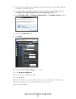
Page 40: ...r http display IP address 85 5 Enter User Name Dak and Password DakPassword in the Windows Security window 6 Click Logon to connect to the display refer to the help file for additional information about the configuration utility 7 Click the Configuration tab 8 Click eth0 9 Select Obtain an IP address automatically 10 Click Upload Configuration 11 Log out of the configuration utility 12 Turn off di...

Page 41: ...yFind utility should have a green check mark See the explanations below for what each item means If an item has a red X next to it click it for additional information or to access the download The Current User Is Not An Administrative User On This Computer Must have administrative rights to install SilverlightTM Once SilverlightTM is installed administrative rights are not necessary Windows Firewa...

Page 42: ...d in the bottom window of the utility 4 Click the desired display VIP5 xx xxx to launch the configuration utility within your web browser Note Refer to the configuration utility help file for additional information After running DisplayFind to determine the display s static IP address reconfiguration of the computer to the same IP address range and subnet may be required 5 Follow the steps in the ...

Page 43: ...er for DHCP 3 Turn on the display Note Both the display and the computer should timout searching for a DHCP server and fall back to auto IP addresses of 169 25x x x 4 Observe boot sequence reconfigure computer to same in the IP address range as the display and same subnet 5 Manually enter IP address in web browser http display IP address 85 or see the Configuration Using DisplayFind To Discover Th...

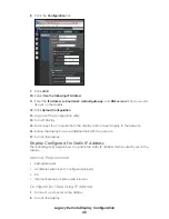
Page 44: ...Disconnect the computer from the display and connect display to the network 16 Ensure the display has an established link with the network 17 Turn on the display Display Configured For Static IP Address The following steps explain how to update the static IP address that is currently set on the display Network Requirements Existing Network Available network port configured properly PC Internet Exp...

Page 45: ...d To Discover The Display p 37 section 5 Enter User Name Dak and Password DakPassword in the Windows Security window 6 Click the Configuration tab 7 Click eth0 8 Change the IP address settings to new values 9 Click Upload Configuration 10 Log out of the configuration utility 11 Turn off display 12 Disconnect the computer from the display and connect display to the network 13 Ensure the display has...

Reviews: