8
Electrical Installation
To access the internal components of the control enclosure, first loosen the 6 screws with a
Philips head screwdriver, and then use the handle to lift the enclosure cover up and away so
the screws pass through the keyholes.
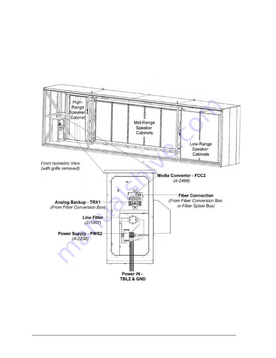
for component and connection locations within the sound cabinet and
control enclosure and
Drawing B-1082599
in
Appendix A
for a detailed wiring schematic.
Power
The system requires three (3) 20 amp 208/230/240 circuits (50 or 60 Hz); 2W + GND per
circuit. Power wiring must be run in conduit up into the bottom of the sound cabinet and
terminated at TBL2. Refer to
Detail “F”
of
Drawing C-984140
.
Figure 12:
Control Enclosure Components & Connections (Covers Removed)


