Troubleshooting
22
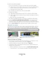
Verifying Network Activity
•
P1
LED will light amber to indicate the switch has power. Refer to
. If this
LED does not light:
• Verify proper connections to power supply (Red to V1+, Black to V1-).
• Verify power supply is supplying 24 VDC.
• Try connecting power to V2 inputs (Red to V2+, Black to V2-), and verify P2 lights.
•
Port 1 (100M)
LED will light solid green to indicate a functional connection between
the fiber box and control enclosure (switch to switch). Refer to
. If this LED
does not light:
•
Switch fiber pairs at the fiber conversion box.
•
Test fiber cable, and terminate as necessary.
•
Remove fiber jumpers.
• Verify power and connectivity at the other end of the switch.
• If still not lighting, replace the switch.
• Each Ethernet jack also has an LED that will light green when a cable to other
equipment is connected. Refer to
. If these LEDs are not lighting:
• Check Ethernet cable/connections.
• Verify connection on opposite end of Cat5e cable.
• Connect known working cable and equipment (such as a diagnostic laptop).
• If still not lighting, replace the switch.
Input/Output Expander
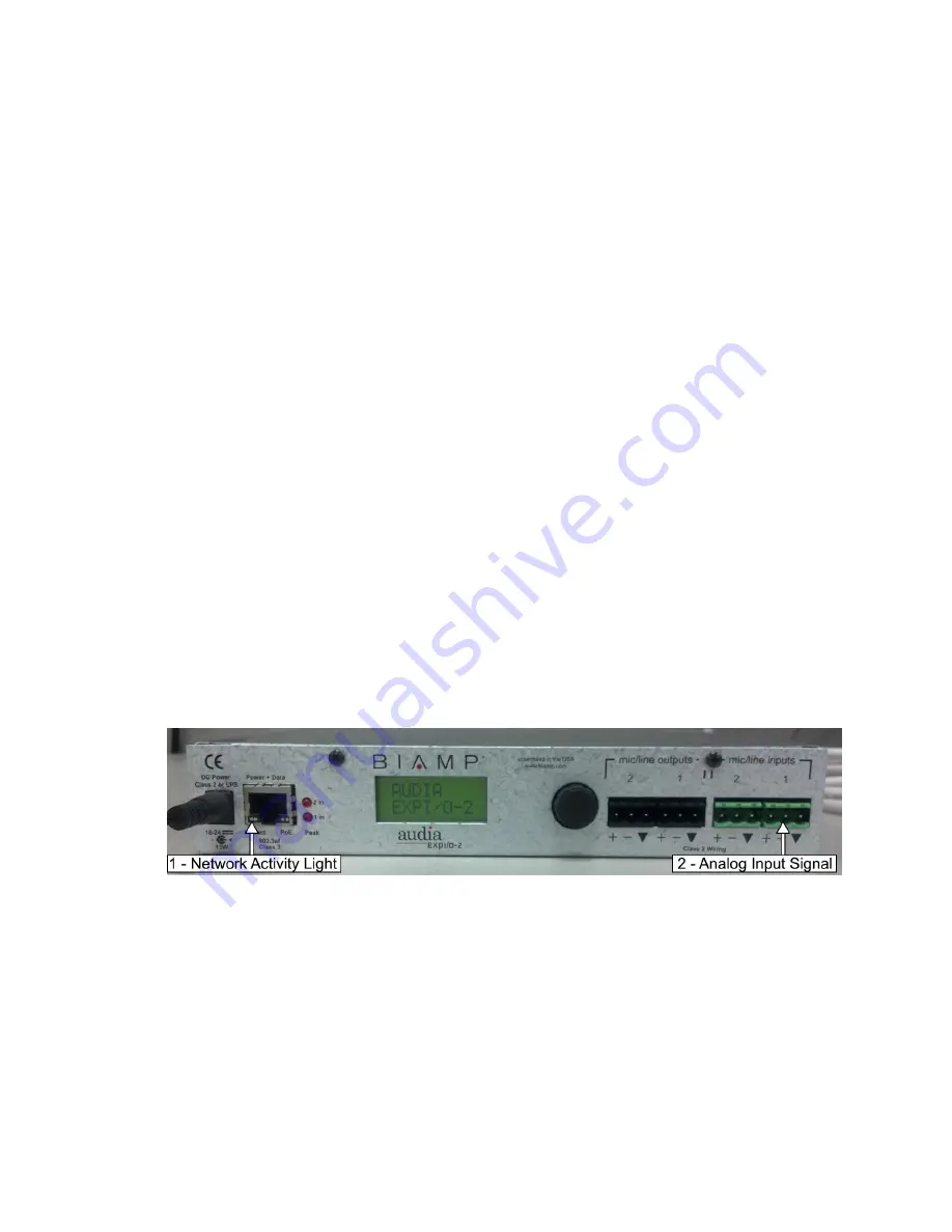
The fiber box (if included in the system) features an input/output expander that converts
the analog audio signal from the control rack into a digital audio signal that can be sent
over a local network. Looking at the connections and LED indicators on these devices
help with system troubleshooting.
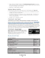
Figure 34:
Network Activity & Analog Input
Typical Component Settings
Use the rotary dial and LCD screen to verify the following settings:
• Bundle # TX = 00001
• Bundle # RX = 00000 (default)
• CobraNet Latency = 5.33ms
• Input Gain CH1 & CH2 = (+12 dBu)
• Phantom Power = OFF (default)
• Output Gain CH1 & CH2 = 0 dBu (default)
Summary of Contents for SPORTSOUND 500HD
Page 32: ...This page intentionally left blank ...
Page 37: ......
Page 42: ...This page intentionally left blank ...
Page 50: ...This page intentionally left blank ...
Page 52: ...This page intentionally left blank ...


