Mechanical Installation
6
Horizontal Wall Mounting (Indoor Only)
Reference Drawings:
Strut Spacing, Horizontal Wall Mounting ..........................................................
DWG-129905
End Bracket Attachment, Horizontal Wall Mounting ......................................
DWG-129906
Horizontal Wall Mounting, Final Steps ...............................................................
DWG-129907
Use this method when the overall display has modules mounted side by side.
1�
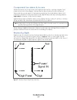
Before attaching the digit module to the wall, attach the caption module to the digit
Installing Caption Modules (p�4)
Note:
Extra strut length is not required when caption modules are mounted at either
the top or bottom of the column.
2�
Attach mounting struts to the wall. Strut length will vary depending on the total
number of display modules. Refer to
DWG-129905
to determine strut length and the
center-to-center distance between the struts.
3�
Attach the end brackets to the right end of all the modules in the left column. Next,
attach brackets to the left end of all the modules in the right column. Refer to
DWG-
129906
.
4�
Use 3/8" bolts to attach the modules in the left column to spring nuts in the struts
(
). Mount the lowest module first, and then add modules working upward.
5�
Starting with the bottom-right module, insert the screw heads on the end brackets of
the left side of the cabinet into the keyholes on the mating bracket of the right side of
the left column cabinet, and press down on the right side until both cabinets are flush
and level horizontally. Refer to
DWG-129907
.
6�
Once the right column cabinet is joined to the left column cabinet, use 3/8" bolts to
attach the right end of the right column module to spring nuts in the struts (
7�
Repeat
Steps 5–6
for all remaining right column modules, working upward.
Corner-Mounting (Indoor Only)
Reference Drawings:
Corner Mount ......................................................................................................
DWG-130508
If the display is to be mounted across the corner of adjoining walls, corner-mounting
brackets may be ordered as an option.
DWG-130508
details this type of mounting.
Multi-line display models that use a single vertical arrangement of modules may be
mounted with corner brackets. However, horizontal display configurations cannot be
mounted across a corner using the simple brackets. Such displays must be attached
to a structure or framework that spans across the corner and safely supports the entire
display. This type of mounting must be designed by a qualified engineer.
Summary of Contents for SW-2001
Page 30: ...This page intentionally left blank ...
Page 32: ...This page intentionally left blank ...
Page 33: ......
Page 34: ......
Page 35: ......
Page 36: ......
Page 37: ......
Page 38: ......
Page 39: ......
Page 40: ......
Page 41: ......
Page 42: ......
Page 43: ......
Page 44: ......
Page 45: ......
Page 46: ......
Page 47: ......
Page 48: ......
Page 49: ......
Page 50: ......
Page 51: ......
Page 52: ......
Page 53: ......
Page 54: ...This page intentionally left blank ...
Page 56: ...This page intentionally left blank ...
Page 57: ......
Page 58: ......
Page 60: ......
Page 61: ......
Page 63: ......
Page 64: ......
Page 65: ......
Page 66: ......
Page 67: ......
Page 68: ......
Page 69: ......
Page 74: ......
Page 75: ......
Page 77: ......
Page 82: ...This page intentionally left blank ...


