background image


Scoreboard Troubleshooting 

19 

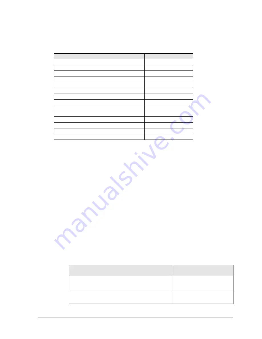
4.7  Replacement Parts List 

Refer to the following table for Daktronics scoreboard replacement parts. 
 

Description 

Daktronics Part # 

Horn, 120V with capacitor 

0A-1152-0332 

Main clock, start/stop switch 

0A-1166-0003 

LED driver, 16-column 

0P-1150-0126 

PanaView Digit, 13” red LED, 7-seg 

0P-1230-0052 

PanaView Digit, 13” amber LED, 7-seg 

0P-1230-0053 

UniView Digit, 13

” Red LED, 7-seg 

0P-1230-0027 

UniView Digit, 13

” Amber LED, 7-seg 

0P-1230-0028 

UniView Colon, Amber 

0P-1230-0069 

PanaView Colon, Amber 

0P-1230-0071 

Transformer, 120P/16S, 6.3 A 

T-1066 

Cable, 20' phone plug 

W-1236 

Cable, 50' phone plug 

W-1237 

Cable, 30' phone plug 

W-1238 

Cable, 10' phone plug 

W-1340 

4.8  Daktronics Exchange and Repair & Return Programs 

Exchange Program 

The Daktronics Exchange Program is a service for quickly replacing key components in need 
of repair. If a component fails, Daktronics sends a replacement part to the customer who, in 
turn, returns the failed component to Daktronics. This decreases equipment downtime. 
Customers who follow the program guidelines explained below will receive this service.


Before Contacting Daktronics 

Identify these important numbers: 
 

Display Serial Number:  _________________________________________________________  
Display Model Number: _________________________________________________________  
Job/Contract Number: __________________________________________________________  
Date Installed: _________________________________________________________________  
Daktronics Customer ID Number: ________________________________________________  
 

To participate in the Exchange Program, follow these steps. 
 

1.


Call Daktronics Customer Service.  


Market Description 

Customer Service Number 

Schools (including community/junior colleges), religious 

organizations, municipal clubs and community centers 

877-605-1115 

Universities and professional sporting events, live events 

for auditoriums and arenas  

866-343-6018 


Summary of Contents for Tuff Sport VB-2101

Page 1: ...Daktronics Drive PO Box 5128 Brookings SD 57006 5128 Tel 1 800 DAKTRONICS 1 800 325 8766 Fax 605 697 4746 Web www daktronics com Daktronics Tuff Sport Volleyball LED Scoreboards Display Manual ED 13515 Rev 4 16 July 2012 ...

Page 2: ......

Page 3: ...means graphic electronic or mechanical including photocopying taping or information storage and retrieval systems without written permission of the publisher All Sport Tuff Sport UniView and PanaView are trademarks of Daktronics Inc Please fill in the information below for your display use it for reference when calling Daktronics for assistance Scoreboard Serial No ________________________________...

Page 4: ......

Page 5: ...ation Overview 9 3 2 Power 9 Grounding 9 3 3 Power On Self Test POST 9 Radio Settings 9 3 4 Scoreboard Signal Connection 10 Section 4 Scoreboard Troubleshooting 11 4 1 Troubleshooting Table 11 4 2 Component Location Access 13 4 3 Replacing Digits 13 PanaView 14 UniView 15 4 4 LED Drivers 16 Replacing a Driver 18 Setting the Driver Address 18 4 5 Segmentation Digit Designation 18 4 6 Schematics 18 ...

Page 6: ...lay Troubleshooting Table 24 6 4 Power Signal Summary 25 6 5 Component Locations Access 25 6 6 Display Drivers 25 Diagnostic LEDs 26 Replacing a Driver 26 6 7 Modules 27 Replacing Modules 27 6 8 Power Supplies 28 Replacing a Power Supply 28 6 9 Display Maintenance 28 6 10 Replacement Parts List 28 Appendix A Reference Drawings 29 Appendix B Scoreboard Options 31 Appendix C Daktronics Warranty and ...

Page 7: ...wer when not in use or when servicing Disconnect display power before servicing power supplies to avoid electrical shock Power supplies run on high voltage and may cause physical injury if touched while powered Do not modify the scoreboard structure or attach any panels or coverings to the scoreboard without the express written consent of Daktronics Inc Project specific information takes precedenc...

Page 8: ...mber suffix that refers to indoor outdoor status power supply and digit color VB Volleyball 1 4 Resources Figure 2 illustrates a Daktronics drawing label The drawing number is located in the lower right corner of a drawing This manual refers to drawings by listing the last set of digits and the letter preceding them In the example the drawing would be referred to as Drawing C 325405 Reference Draw...

Page 9: ...PXX Following the Replacement Parts List is the Daktronics Exchange Policy and the Repair Return Program Refer to these instructions if replacing or repairing any display component 1 6 Product Safety Approval Daktronics Tuff Sport scoreboards are ETL listed tested to CSA standards and CE labeled for indoor use Contact Daktronics with any questions regarding the testing procedures 1 7 Specification...

Page 10: ......

Page 11: ...oreboard section Daktronics indoor scoreboards use 3 8 eyebolts Daktronics strongly recommends using a spreader bar or lifting bar to lift the display Spreader bars ensure the force on the eyebolts remains straight up minimizing lifting stress Figure 4 illustrates the preferred scoreboard lifting method on the left and an acceptable alternative lifting method on the right When lifting the display ...

Page 12: ...nticipate a user s individual installation needs or provide mounting hardware suitable for every installation Choose a method of installation that will safely support the weight of the display 2 3 Suspension Mounting Kit One of several mounting options with the Tuff Sport scoreboards is a suspension lift eye installation which requires a special mounting kit part 0A 1237 0016 Contact Daktronics ab...

Page 13: ...ng similar to Scoreboard Mounting shown above or Drawing A 156134 for instructions on mounting ad panels directly to the top or bottom of a scoreboard 2 6 Scoreboard Protective Devices Daktronics Tuff Sport displays have been designed so that a normal basketball or volleyball impact will not damage the LEDs or display cabinet reducing the need for protective devices Some users however may still wi...

Page 14: ......

Page 15: ...otects the equipment against damaging electrical disturbances and lightning Daktronics recommends a resistance to ground of 10 ohms or less The electrical contractor performing the electrical installation can verify ground resistance Daktronics Sales and Service personnel can also provide this service The grounding connection on the power cord s three prong plug connects to the shell of the scoreb...

Page 16: ...ary scoreboards lets operators control several displays with one controller and they can also switch jacks to control individual boards using multiple controllers 2 Route the cable from the J box on the control console end to a J box near the display 3 Install the 1 4 phone plug Daktronics part 0L 40683 to the scoreboard end of the cable Be sure to connect the cable shielding only in the J box on ...

Page 17: ...rmation provided in Section 4 8 Problem Possible Cause Solution Items to Check Scoreboard doesn t light and console doesn t work No power to the scoreboard Check that the main circuit breaker for the scoreboard is on Check that the scoreboard is receiving 120 or 230 VAC power No power to console Ensure the console is plugged into a 120 or 230 VAC power supply Swap the console with one known to wor...

Page 18: ... the scoreboard model Refer to the control console operation manual see Section 1 1 Incorrect driver address Check that the scoreboard driver s are set to the correct address es see Section 4 4 Scoreboard digits light console works but no display on scoreboard No wired signal from console See solution on previous page No radio signal from console See solution on previous page Bad damaged wiring Ch...

Page 19: ...display Digit panels are typically held in place on the scoreboard face by two screws To remove a digit simply unfasten the screws and carefully lift it from the cabinet The power signal plug can then be removed from the connector on the back of the digit to completely free the digit and access internal components Remove non digit access panels by unfastening the top side or bottom screws holding ...

Page 20: ...ing the digits to the inside of the panel and then lift the digit off the stud inserts 4 Position a new digit over the studs making sure the small plastic spacers are still in place and tighten the nuts 5 Reconnect the power signal connector Note This is a keyed connector and it will attach in one way only Do not attempt to force the connection 6 Secure the digit panel to the display with the two ...

Page 21: ...um standoffs and then lift the digit off the standoff diffuser assembly 4 Position a new digit over the standoffs and tighten the nuts It may be necessary to also tighten the standoffs if they became loose while removing the nuts 5 Reconnect the power signal connector Note This is a keyed connector and it will attach in one way only Do not attempt to force the connection 6 Secure the digit panel t...

Page 22: ...iew the location and components of a Tuff Sport driver enclosure The Tuff Sport scoreboards in this manual use 16 column drivers Figure 10 Each driver has numerous connectors providing power and signal inputs and outputs to the scoreboard digits and indicators Connector Function 1 16 Output to digits and indicators 17 Control signal 18 Control for horn 19 Address Figure 10 Driver Enclosure Locatio...

Page 23: ...dy on DS1 will be on and steady to indicate the driver has power DS2 Red Signal RX Steady on or blinking DS2 will be on or blinking when the driver is receiving a signal and off when there is no signal DS3 Amber Status Blinking DS3 will be blinking at one second intervals to indicate the driver is running Note While it is necessary to have the scoreboard powered on to check the LED driver status i...

Page 24: ...the driver has resolved the problem Setting the Driver Address Since the same LED drivers can be used for many scoreboard models each driver must be set to receive the correct signal input or address for the model being used This address is set with jumper wires in a 12 pin plug which mates with jack J19 on the driver Figure 12 Note The scoreboards in this manual must be set to address 17 Refer to...

Page 25: ... fails Daktronics sends a replacement part to the customer who in turn returns the failed component to Daktronics This decreases equipment downtime Customers who follow the program guidelines explained below will receive this service Before Contacting Daktronics Identify these important numbers Display Serial Number _________________________________________________________ Display Model Number ___...

Page 26: ... items not subject to exchange Daktronics offers a Repair Return Program To send a part for repair follow these steps 1 Call or fax Daktronics Customer Service Refer to the appropriate market number in the chart listed on the previous page Fax 605 697 4444 2 Receive a case number before shipping This expedites repair of the part 3 Package and pad the item carefully to prevent damage during shipmen...

Page 27: ...ed in an empty area so be sure to set the volume according to the acoustics of the facility 5 2 Visual Horn Indicator VHI In addition to the horn Daktronics offers a visual horn indicator VHI that lights up when the buzzer sounds To install the VHI users must tap into the existing horn wiring to provide power and signal For more information about installing the VHI option including details on the ...

Page 28: ...captions are on changeable panels that fit into retainers mounted above and below the standard captions If these retainers are not already present attach the retainers included with the caption kit Caption kits are also available for certain statistics display models to switch between basketball volleyball wrestling and hockey modes Refer to Drawing A 150021 in Appendix B for changeable caption in...

Page 29: ...at allow users to show custom Home and Guest names or messages of 15 characters on the scoreboard in place of static vinyl captions TNMCs are typically ordered factory installed but they may also be field mounted after the scoreboard is in place Characters are shown on one line using single or double stroke fonts Primary matrix size is 8x48 with 0 75 pixel spacing Figure 13 shows an example of TNM...

Page 30: ...tion 4 8 Symptom Condition Possible Remedy One or more LEDs on a single module fails to light Check replace the ribbon cables on the module Replace the module see Section 6 7 One or more LEDs on a single module fails to turn off Check replace the ribbon cables on module Replace the module see Section 6 7 A section of the display not working section extends all the way to the right side of the disp...

Page 31: ...e Home display power supply and then to the Guest display power supply 3 Power from the power supplies is relayed to all display modules 4 The modules draw their power directly from the power supply assemblies the display driver receives power out from the first module via ribbon cable 6 5 Component Locations Access Reference Drawings Installation 6 Amber 8x48 TNMC Drawing A 148701 To access the i...

Page 32: ...ibed in Section 6 5 2 Disconnect all power and signal connectors from the driver by squeezing together the locking tabs and pulling the connectors free Note It may be helpful to label the cables to know which cable goes to which connector when reattaching a driver 3 Remove the four screws securing the driver to the module This will be the right most module when viewing the display from the front 4...

Page 33: ...nnectors free Note It may be helpful to label the cables to know which cable goes to which connector when reattaching 3 Remove the nuts securing the module circuit board to the face panel If a display driver is attached to the module remove it along with the screws and standoffs 4 Position a new module on the front of the face panel and reconnect all ribbon cables 5 Reattach the module to the face...

Page 34: ...s the following issues Loose Hardware Verify that fasteners such as bolts and rivets have not come loose Check and tighten or replace fasteners as required Excessive Dust Buildup It may be necessary to occasionally vacuum the inside of the display cabinet to remove dust dirt buildup that may interfere with airflow Corrosion Check the paint and look for possible corrosion Note If any of the precedi...

Page 35: ...m AS5000 BB VB and WR 1 A 124686 Block Diagram AS5000 BB VB and WR 3 A 124688 Schematic Dual 1 4 Phone J box w Shunt Jack A 125316 Block Diagram A S 3000 or 5000 BB VB and WR 2 A 125415 Block Diagram A S 3000 or 5000 BB VB and WR 4 A 125417 16 Column LED Driver II Specifications A 126174 Schematic 16V 1 Driver 120 or 230VAC A 158348 Mechanical Spec VB 2101 A 170489 Electrical and Signal Spec VB 21...

Page 36: ......

Page 37: ......

Page 38: ......

Page 39: ......

Page 40: ......

Page 41: ... 7 5 9 7 5 9 0 5 60 255 7 6 1 5287 1 25 6 7 67 76 3 1 6 x x x ...

Page 42: ......

Page 43: ......

Page 44: ......

Page 45: ......

Page 46: ......

Page 47: ......

Page 48: ......

Page 49: ... Schematic 3 4 and 1 DC TNMC s B 146975 Advertising Identification Display Mounting A 147668 Suspension Lift Eye Installation A 148644 Installation 6 Amber 8x48 TNMC A 148701 12V DC Horn Option Installation A 148960 Changeable Team Name Caption Installation A 150021 Corner Mounting A 150831 ID or Ad Panel Mounting to Scoreboard A 156134 ...

Page 50: ......

Page 51: ......

Page 52: ......

Page 53: ......

Page 54: ......

Page 55: ......

Page 56: ......

Page 57: ......

Page 58: ......

Page 59: ......

Page 60: ......

Page 61: ...Daktronics Warranty and Limitation of Liability 33 Appendix C Daktronics Warranty and Limitation of Liability ...

Page 62: ......

Page 63: ... back to the Purchaser All returns must be pre approved by Daktronics before shipment Daktronics shall not be obligated to pay freight for any unapproved return Purchaser shall pay any upgraded or expedited transportation charges D Any replacement parts or Equipment will be new or serviceably used comparable in function and performance to the original part or Equipment and warranted for the remain...

Page 64: ... principles of contract tort or statutory duty principles of indemnity or contribution or otherwise In no event shall Daktronics be liable to Purchaser or any other party for loss damage or injury of any kind or nature arising out of or in connection with this Warranty in excess of the purchase price of the Equipment actually delivered to and paid for by the Purchaser The Purchaser s remedy in any...

Reviews: