background image

201 Daktronics Drive

Brookings, SD 57006-5128

www.daktronics.com/support

800.325.8766

GENERIC SERVICE VM-1020 

AND DDMS CABINET

DISPLAY SYSTEM MANUAL

17 October 2018

DD3933514

Rev 00

Summary of Contents for VM-1020 Series

Page 1: ...201 Daktronics Drive Brookings SD 57006 5128 www daktronics com support 800 325 8766 GENERIC SERVICE VM 1020 AND DDMS CABINET DISPLAY SYSTEM MANUAL 17 October 2018 DD3933514 Rev 00 ...

Page 2: ...part of this book covered by the copyrights hereon may be reproduced or copied in any form or by any means graphic electronic or mechanical including photocopying taping or information storage and retrieval systems without written permission of the publisher Daktronics trademarks are property of Daktronics Inc All other trademarks are property of their respective companies ...

Page 3: ...nduit 7 5 Electrical Installation 8 Getting Started 8 AC Power for Sets with One DDMS Cabinet 8 Grounding 8 Power 8 LIE Termination 9 AC Power 9 Signal 9 Interconnections at DC Terminal Assembly 9 DC Power and Ground 9 Signal 9 6 Control Equipment Configuration 10 DDMS Controller Connections 10 DDMS Controller Communications J4 J7 J11 and J12 10 Central Control Port J6 and J7 10 Auxiliary Control ...

Page 4: ...to Wire Enclosure 21 Maintenance Checklist 22 Troubleshooting 23 9 Replacement Parts and Exchange and Repair Programs 25 Daktronics Part Numbers 25 Tools 25 Module Replacement 26 DDMS Controller Replacement 26 Power Supply Assembly Replacement 27 Fan Assembly Replacement 27 Light Assembly Replacement 27 VM CAN Distribution Board Replacement Optional 27 Daktronics Exchange and Repair Return Program...

Page 5: ...d on the cover page of each manual For example this manual is referred to as DD3933514 The serial and model numbers for the display are on the ID label attached to the display This label looks similar to Figure 1 When calling Daktronics Customer Service please have this information available to ensure timely response Daktronics builds displays for long life and they require little maintenance Howe...

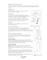
Page 6: ...s provide versatility allowing for many configuration options Your DDMS equipment list may include only one DDMS cabinet or it may include a variety of cabinets one for power one for control equipment and one for remote control Power and Control Enclosure The power and control enclosure contains the equipment needed to operate a DDMS set all within an enclosure smaller than a typical traffic cabin...

Page 7: ...c cabinets to provide a secondary control location The LIE contains an ACP and outlets LIEs are designed to be pole mounted Cabinet Light The DDMS cabinet is equipped with a fluorescent light located on the top rack of the cabinet The door switch in the DDMS cabinet activates the light when the door opens DC Terminal Assembly Signal and DC power route to the LED panel s from the DC terminal assemb...

Page 8: ...ind the door on the side designated as rear Utility power terminates in the power entry box Power Supply Assembly Each DDMS set contains two power supply assemblies Each power supply assembly contains one power supply and one isolation board Power Supply The power supplies provide voltage to power the LED panels Multiple power supplies provide power redundancy If one power supply fails the other i...

Page 9: ...trol Panel ACP The Vanguard auxiliary control panel ACP is an interface to the DDMS controller VM CAN Distribution Board Optional The VM CAN distribution board is located in the optional fiber to wire enclosure refer to Figure 5 This board converts fiber optic cable routing from the DDMS cabinet to copper wire as required by the LED panel s Figure 5 Fiber to Wire Enclosure ...

Page 10: ...e bottom of the cabinet allows for water drainage Do not seal the cabinet to the concrete pad as this prevents water from draining properly Conduit entering the cabinet should be sealed to prevent dust objects and small animals from entering the cabinet The conduit for power and signal enter through the open area in the bottom of the cabinet Pole Mounting Mount the cabinet using the pole mount bra...

Page 11: ...alling conduit and power and signal cables The size of conduit routing from the DDMS cabinet s varies depending on the number of LED panels in the set The contractor may choose which type of conduit material to use unless DC power is in use AC Power Conduit The contractor may choose which type of conduit material to use DC Power Conduit Contact Daktronics for information on which size conduit is n...

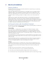
Page 12: ...refer to LIE Termination Grounding All components of a display system including but not limited to displays control equipment and connected peripheral equipment must be electrically grounded Only qualified individuals may perform electrical work including verification of ground resistance Daktronics is not responsible for improper grounding or damage incurred as a result of improper grounding Grou...

Page 13: ... on the DDMS controller to J2 on the ACP Interconnections at DC Terminal Assembly DC Power and Ground 24 VDC power and ground connections route from the DC terminal assembly in the DDMS cabinet to the LED panels To install DC power wires 1 Route and connect the DC cables from the power supplies to the DC breaker rail 2 Route and connect the DC cable from the DC breaker rail to the DDMS controller ...

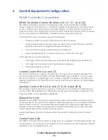
Page 14: ...ral control port is used as the primary communication channels between the central controller and the DDMS controller Either RS232 J6 or RS422 J7 can be used The port is capable of interfacing to any number of media converters or modems The default configuration for this port is Point to Multi Point Protocol PMPP no handshaking at 9600 bps Auxiliary Control Port J5 A and J5 B J8 A and J8 B The aux...

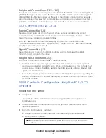
Page 15: ...nection J2 The ACP connects to J14 on the DDMS controller via Cat 5 cable with an RJ45 termination and a straight thru pinout Peripheral Connections J3 Peripheral connections can be made at these locations The CAN network supports a group of devices that communicate over a pair of signal wires connected parallel to each other Each device on a CAN network must have a unique address For DDMS systems...

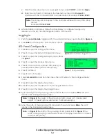
Page 16: ...d Green tricolor LED panels 6 Press 1 for Gen 4 7 Press 1 for 7 x 5 modules 8 Select 66 mm LED panels from the menu The ACP returns to the Configure Display menu 9 Press 2 to open the Display Type menu 10 Press 2 for Line The ACP returns to the Configure Display menu 11 Press 3 to open the Display Pixel Height menu 12 Type the height of the grouping of LED panels in the set and press Enter The ACP...

Page 17: ...Matrix Figure 9 14 x 20 Matrix 14 Press 5 to open the Display Access menu 15 Press 4 for Front The ACP returns to the Configure Display menu 16 Press 6 and enter the set s address in the Display Address menu The ACP returns to the Configure Display menu ...

Page 18: ...deletion and start the auto detection procedure When this procedure completes you can view the peripherals by pressing 4 on the keypad from the Diagnostics menu or by pressing 2 on the keypad from the Peripheral Configuration menu Communication Configuration The Communication Configuration menu enables configuration items such as communication protocol to be set To navigate to the Communication Co...

Page 19: ...it may be set to Full or Half Duplex and 10 Mbps or 100 Mbps Standard Protocol is TCP IP and UDP IP but the controller can use a port server with a serial TCP IP protocol as well IP Settings IP addresses and ports may be changed in the IP Settings menu refer to Figure 12 Once an option is set the controller performs a soft reset Press the number of the field to change Figure 13 illustrates the Con...

Page 20: ...ffic cabinet door for at least 10 seconds Open the door and immediately check that Door Switch 1 reports as Closed 8 Check that both isolation boards report status as 24 0 V or higher 9 Press Esc to return to the Diagnostics menu and press 1 to open the Test Patterns menu Press 2 to run the Auto Test Visually check that all pixels display properly on all LED panels When complete press 1 to return ...

Page 21: ...block positions in the power entry box inside the control cabinet Replace the cover on the power entry box 2 Turn on AC power to the site and check that all circuit breakers in the panelboard in the power cabinet and control cabinet are on 3 On the DC terminal assembly check that all breakers with wires connected to them are turned on 4 With all LED panel doors open log into the ACP Press 2 to ope...

Page 22: ...heck that the AC power surge suppressor in the power cabinet Surge Suppressor 2 reports Pass 15 Check the time and date in the controller and set them if they are incorrect 16 Test the communication system with the central controller a Have the central controller operator call the DDMS controller download a new test message that will not misdirect traffic into the controller and display the messag...

Page 23: ...es Note Ground meters for this test are available for purchase from Daktronics Cabinet Check for water stains and other signs of water intrusion Seal any leaks that have developed with a silicone sealant or another suitable sealer Repair any door gaskets that have tears or missing pieces Check the drainage holes in the bottom of the cabinet for obstructions Fan Check that the fan works by pressing...

Page 24: ...g Method Cleaning supplies Water 5 gal bucket Automotive detergent 4 to 8 telescoping soft automotive brush with bristles that are light to medium in rigidity Several soft terry cloth towels Cleaning process 1 Mix the automotive detergent and cold water in the 5 gal bucket at 1 oz detergent to 1 gal of cold water Distilled water is preferred but not required 2 Dip the brush in the bucket of soapy ...

Page 25: ...to check for hardware problems and incorrect variable settings Note The following tests display functions not other DDMS equipment hardware 1 Connect to the DDMS controller 2 Check that the temperature levels shown on the Sign Status screen of the Sign Control tab are the appropriate values 3 Perform a diagnostics test and check that all the power supplies and other configured peripherals pass 4 M...

Page 26: ...g routine maintenance table may be filled out for each set Set Location Maintenance Item Monthly Remote Diagnostics 1 yr As Needed Dates Performed and Initials Earth Ground Resistance X DDMS Cabinet X Fan X Filter X DDMS Controller X ACP X LED Panel Cabinet X LED Panel Face X LED and Electronic Circuitry X Fiber to Wire Enclosure X ...

Page 27: ...it breaker in the panelboard is on and is not tripped The DDMS controller or modem is bad Replace the DDMS controller or modem No LEDs light but the DDMS controller communicates with the central controller All peripherals indicate Communication Error The DDMS controller is bad Refer to the DDMS controller operation manual LEDs on the LED panel s are garbled or the wrong LEDs are on The signal conn...

Page 28: ...ntroller is bad Replace the DDMS controller A pixel test shows all pixels on all LED panels as bad The LED panels play messages correctly The fiber or RS422 LED panel connections are not terminated properly Re terminate the LED panel connections The DDMS controller is bad Replace the DDMS controller The internal temperature sensor is not reading The temperature sensor is not configured correctly C...

Page 29: ...r in a single enclosure 0Z _ _ _ _ _ _ _ _ denotes an assembly W _ _ _ _ denotes a wire or cable Cables may also carry the assembly numbering format in certain circumstances This is especially true of ribbon cables PR _ _ _ _ _ _ _ denotes a specially ordered part Most circuit boards and components within this DDMS set carry a label listing the part number of the unit If a circuit board or assembl...

Page 30: ...nnectors into the new module Note The connectors only fit together one way do not force the connection 7 Reapply power to the LED panel by turning on the circuit breaker s turned off in Step 1 8 Test the modules using the ACP LCD Simulator a Display the moving row moving column and all on all off test messages Run the test messages at both 10 and 100 brightness settings Watch for proper operation ...

Page 31: ...bly Replacement 1 Turn off power to the fan assembly by turning off the appropriate breaker in the panelboard 2 Disconnect the fan s power cord 3 Remove the hardware securing the finger guard and fan to the assembly bracket 4 Remove the fan 5 Attach the new fan to the bracket and secure it using the hardware removed in Step 3 Note the air flow orientation when attaching the new fan Airflow should ...

Page 32: ...rvice 2 When the new exchange part is received mail the old part to Daktronics If the replacement part fixes the problem send in the problem part which is being replaced a Package the old part in the same shipping materials in which the replacement part arrived b Fill out and attach the enclosed UPS shipping document c Ship the part to Daktronics 3 A charge is made for the replacement part immedia...

Page 33: ...ct a services coordinator via phone email or by creating a MySupport account on the Daktronics website This expedites repair of the part 3 Package and pad the item carefully to prevent damage during shipment Electronic components such as printed circuit boards should be placed in an antistatic bag before boxing Daktronics does not recommend using packing peanuts when shipping 4 Enclose your name a...

Page 34: ...hed to the top of the LED panel cabinet for lifting Fire to Wire Enclosure A cabinet that contains the VM CAN distribution board which converts fiber cable to copper wire as required by the LED panel s Isolation Board A component that distributes DC power from the power supplies to the LED panels Laptop Interface Enclosure LIE An enclosure that provides a control location away from the DDMS cabine...

Page 35: ...ressor A component that protects the LED panel s from voltage spikes on the utility power input at the DDMS cabinet Traffic Cabinet An enclosure that includes control and can include power equipment needed to operate a DDMS site with extra room for customer provided equipment Depending on the type traffic cabinets can be either ground or pole mounted Vanguard Daktronics trademarked name for DMS an...

Reviews: