Control Equipment Configuration
12
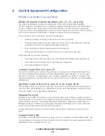
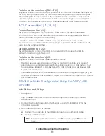
c.
Click the drop-down menu in lower-right corner, select
TCP/IP
, and click
Open
.
d.
Enter the controller’s IP address in the free-text box then click
Connect
to
interface with the controller. DDMS controller default IP address:
172.16.192.25
4.
After installation and setup, follow the steps below to configure the sign. Any
reference to the ACP is interchangeable with LCD Simulator.
Logging In
1.
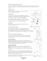
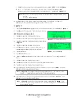
Push the
Local/Remote
toggle switch; the Local Mode menu opens. Refer to
.
2.
Press
Enter
on the keypad. The Main Menu opens.
LED Panel Configuration
1.
Press
4
to open the Configuration menu.
2.
Press
1
to open the System Configuration menu.
3.
Press
1
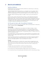
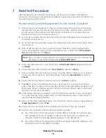
to open the Configure Display menu. Refer
4.
Press
1
to open the Module Type menu.
5.
Press
1
for Monochrome (amber LED panels), or
press
2
for Red-Green (tricolor LED panels).
6.
Press
1
for Gen 4.
7.
Press
1
for 7 x 5 modules.
8.
Select
66 mm LED
panels from the menu. The ACP returns to the Configure Display
menu.
9.
Press
2
to open the Display Type menu.
10.
Press
2
for Line. The ACP returns to the Configure Display menu.
11.
Press
3
to open the Display Pixel Height menu.
12.
Type the height of the grouping of LED panels in the set and press
Enter
. The ACP
returns to the Configure Display menu.
Note:
, the height of the grouping of LED panels is 21. (display pixel
height = 7 pixels high per LED panel × 3 LED panels high).
13.
Type the width of the grouping of LED panels in the set and press
Enter
. The ACP
returns to the Configure Display menu.
Note:
, the width of the grouping of LED panels is 20. In
, the
width of the grouping of LED panels is also 20. (display pixel width = 20 pixels
wide per LED panel).
Note:
The computer connected to the controller will need to be on the same
subnet.
Example:
172.16.192.24
Figure 6:
Local Mode—logged out
Figure 7:
Configure Display


