45
hyDrAuLIC sysTeM
Certain concepts referring to the Italian UNI 10412-2 (2009) Standard are described in this chapter.
As previously described, when installing, all national, regional, provincial and town council Standards in force provided by the
country in which the appliance has been installed must be complied with.
During installation of the stove it is MANDATORy to adjust the system with a manometer in order to display the water pressure.
INsTALLATION AND sAFeTy DeVICes
The installation, relative system connections, commissioning and inspection of correct functioning must be carried out perfectly,
in full compliance with Standards in force, national, regional and municipal, as well as these instructions.
For Italy, installation must be carried out by professionally authorised staff (Ministerial Decree dated 22.01.08 n°37).
Dal Zotto s.p.A. declines all responsibility for damage to objects and/or persons caused by the system.
sAFeTy DeVICes FOr CLOseD VesseL sysTeM
According to the UNI 10412-2 (2009) Standard in force in Italy, the closed systems must have: safety valve, pump control
thermostat, acoustic alarm activation thermostat, temperature indicator, pressure indicator, acoustic alarm, regulation automatic
circuit breaker switch, automatic circuit breaker block switch (block thermostat), circulation system, expansion system, safety
dissipation system incorporated with the generator with thermal safety valve (self-activated), whenever the appliance does not
have a temperature self-adjustment system.
DIsTANCes OF sAFeTy DeVICes ACCOrDINg TO The sTANDArD
The temperature safety sensors must be in place on the machine at a distance no greater than 30 cm from the flow connection.
Whenever the generators lack a device, those missing can be installed on the generator flow pipe, within a distance no greater
than 1m from the machine.
| eNgLIsh
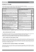
TAbLe OF sAFeTy DeVICes FOr CLOseD VesseL sysTeM
AND NOT PreseNT IN The PrODuCT
Safety valve
R
Pump control thermostat (it is managed by the water
probe and the board program)
R
Acoustic alarm activation thermostat
-
Water temperature indicator (display)
R
Pressure indicator
-
Acoustic alarm
-
Regulation automatic circuit breaker switch (managed
by board program)
R
Minimum and maximum pressure pressure switch
R
Water overheating automatic circuit breaker switch (block
thermostat)
R
Circulation system (pump)
R
Expansion system
R
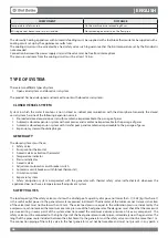
sAFeTy DeVICes
CIrCuIT bOArD
:
Intervenes directly by sending the product into alarm conditions until
complete cooling, in the case of: breakage of flue gas motor, pellet
feed motor breakage, black out (if more than 10 seconds), no ignition
FLOW seNsOr:
In the event of inadequate flow, it takes the machine to alarm conditions
F2.5 A 250V Fuse (sTOVes):
Protect the machine from violent current drops
85°C CALIbrATeD MeChANICAL buLb WITh MANuAL reArM
:
Intervenes by blocking fuel feed whenever the pellet tank t° reaches
the limit of 85°C.
rearm must be performed by qualified staff and/
or the manufacturer's technical after-sales assistance.
100°C CALIbrATeD MeChANICAL buLb WITh MANuAL reArM
:
Intervenes by blocking the fuel feed whenever the t° of the water
inside the product is near to 100°.
rearm must be performed by
qualified staff and/or the manufacturer's technical after-sales
assistance.
MINIMuM AND MAxIMuM Pressure sWITCh
:
Intervenes in the event of inadequate water pressure.
rearm must
be performed by qualified staff and/or the manufacturer's
technical after-sales assistance.
MeChANICAL AIr Pressure sWITCh:
Blocks the pellet in the event of insufficient depression

