5
4
EN
EN
ELIS Z (models with timer)
Basic wiring information:
1) Switch off the electrical circuit you will be working on.
2) Unscrew the screw on the side of the front panel and remove the cover, under which there is a terminal strip with
three terminals.
3) The terminals are labelled with the letters T (interruptible phase), L (fixed phase) and N (neutral phase).
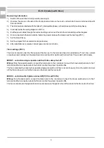
4) Carefully review the wiring diagram in PIC 7a.
5) Pull the power cables through the rubber bushing and connect them to the terminal strip per the diagram.
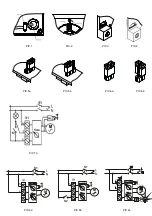
6) Once connected to the terminal strip, fasten the power cables with a clamp near the bushing (PIC 1).
7) Set the timer (Time).
8) Set the jumpers for the selected mode (see below)
9) After installation is complete, connect power and turn on the fan.
Timer settings (PIC 3.)
The timer is located under the front panel of the fan next to the terminal strip and is labelled as “Time”. Use a small
screwdriver and carefully turn the adjustment screw to the left or right to set the timer from 15 seconds to 45 minutes.
MODE 1 – activation using a separate switch with time delay shut-off
Wiring:
From the separate switch, connect the black wire to the L terminal. Connect the brown switched wire to the T
terminal and the blue neutral wire to the N terminal. Set the jumper in position
5a
.
The fan is activated by pressing the separate single-pole switch and then runs continuously. Once the switch is turned
off, the fan continues to run for the time set on the timer and then turns off.
MODE 2 – activation after lights are turned off (PIC 7a and PIC 5b)
Wiring:
From the light switch, connect the black wire to the L terminal. Connect the brown switched wire to the T
terminal and the blue neutral wire to the N terminal. Set the jumper in position
5b
.
The fan is connected to the light switch and is activated once the light is turned off and runs for the time set on the timer.
ELIS ZW (models with timer and humidity control)
Basic wiring information:
1) Switch off the electrical circuit you will be working on.
2) Unscrew the screw on the side of the front panel and remove the cover, under which there is a terminal strip with
three terminals.
3) The terminals are labelled with the letters T (interruptible phase), L (fixed phase) and N (neutral phase)
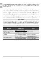
4) Carefully review the wiring diagram in PIC 8a to PIC 8d, depending on the selected mode (see below).
5) Pull the power cables through the rubber bushing and connect them to the terminal strip per the diagram.
6) Once connected to the terminal strip, fasten the power cables with a clamp near the bushing (PIC 2).
7) Set the timer (Time).
8) Set the humidity control (Humidity).
9) Set the jumpers I/II and A/B for the selected mode (see below)
10) After the electrical wiring is installed, test the operation of the fan.
Timer settings (PIC 3.)
The timer is located under the front panel of the fan next to the terminal strip and is labelled as “Time”. Use a small
screwdriver and carefully turn the adjustment screw to the left or right based on the designed timer setting, from 15
seconds to 45 minutes.
Humidity control settings (PIC 4.)
The humidity control is located under the front panel of the fan next to the terminal strip and is labelled as “Humidity”.
Use a small screwdriver and carefully turn the adjustment screw to the left or right to set the switching humidity level for
the fan, from 60% to 100%.
MODE 1 – using the humidity sensor with time delay shut-off (PIC 8a)
Wiring:
Connect the black wire to the L terminal. Connect the blue neutral wire to the N terminal. Position jumper I/II as
shown in
PIC 6b
. Position jumper A/B as shown in
PIC 6a
.
The fan is activated once humidity in the space exceeds the set level. To reduce the humidity below the set level, the
fan continues to run for the time set on the timer and then turns off.
MODE 2 – using the humidity sensor with time delay shut-off and separate switch (PIC 8b)
Wiring:
Connect the black wire to the L terminal. Connect the brown wire from switch S2 to the T terminal and the blue
neutral wire to the N terminal. Position jumper I/II as shown in
PIC 6b
. Position jumper A/B as shown in
PIC 6a
.
The fan is activated once humidity in the space exceeds the set level. To reduce the humidity below the set level, the
fan continues to run for the time set on the timer and then turns off.
Switch operation:
The fan is activated or turned off using switch S2 regardless of the selected mode. If the fan is off, it
is activated using the switch, after which the fan runs for the time set on the timer. It then turns off and returns to
automatic mode. If the fan is running, use the switch to turn it off.
MODE 3 – using the light sensor (on) and humidity sensor with time delay shut-off (PIC 8c)
Wiring: Connect the black wire to the L terminal. Connect the blue neutral wire to the N terminal. Position jumpers I/II as
shown in
PIC 6a
. Position jumpers A/B as shown in
PIC 6a
.
ATTENTION: We do not recommend this mode be used in rooms with windows. Daylight could cause
unwanted switching.
The fan runs for 45 seconds once the lights are turned on, and remains running while they are on. Turning off the lights
activates the time delay shut-off and the fan runs for the time set on the timer.
Summary of Contents for ELIS
Page 35: ...35 ...


