19
EN
EN
The controller must be installed by a qualified professional (electrician) after carefully reading the product manual, and
installation must conform to safety standards.
CAUTION!
The controller's contacts are under voltage. During installation, maintenance, repair and setting, the controller must be
disconnected from the main source of voltage.
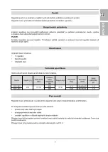
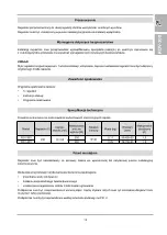
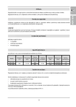
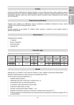
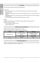
The ROV-400 thyristor speed controller (referred to as the “controller” below) is intended for the continuous control of
the speed of rotation of a fan with a maximum power of 400 W. If you turn the controller to the right (clockwise), you will
reach the highest speed of the fan; if you turn it to the left (counter-clockwise), you will gradually decrease the fan's
speed until the position where you will switch the fan off by a click.
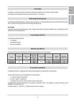
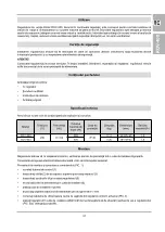
Model
Voltage (V)
Frequency
(Hz)
Maximum
output
power (W)
Degree of
protection
Weight (kg)
Dimensions
(mm)
Maximum
load (A)
ROV-300
230
50 / 60
300
IP 40
0.11
95×85×60
1.5
ROV-400
400
0.25
78×78×63
1.8
Safety requirements
Use
The original packing contains:
•
1 controller
•
Screws with wall plugs
•
User's Manual
•
Original packaging
Contents of the package
The ambient air must not contain explosive and corrosive particles.
Technical specifications
The controller must be placed inside a room vertically on a wall, preferably in a flush-mounted junction box.
Connection to the electric network should be made via an automatic switch (circuit breaker).
Procedure for assembly and connection of the controller (
PIC
. 1):
•
remove the control knob (1)
•
unscrew the nut (2) from the top cover and take off the cover (3)
•
unscrew the screws (4) and remove the controller (5)
•
pull the supply cables through into the junction box (6)
•
install the junction box into the wall
•
insulate the ends of the supply cables at a length of 6–7 mm
•
connect the supply cables into the terminal block located in the controller according to the diagram (
PIC
. 3)
•
place the controller into the junction box in such a way that the terminal block is located in the upper part of the
controller (
PIC
. 2) and fix the screws.
Assembly
ROV
-400
Summary of Contents for ROV-300
Page 18: ...18 BG BG BG 3 5 7 mm 2 5 C 40 C 80 25 C ROV 300...
Page 34: ...34 BG BG BG 2 5 C 40 C 80 25 C ROV 400...
Page 35: ...35...


