17
3.6 Connections
/ connessioni
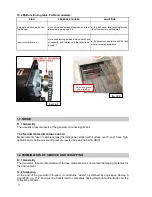
The dimensions of all connections present on the generators, based on the model, are summa-
rised in
tab.3.6
with reference to
fig.3.5
.
POS. Q.tà
DESCRIZIONE
TIPO
UNITA'
DIMENSIONI
Pos.
Q.ty
description
type
unit
dimension
N1
1
mandata
manicotto ISO7/1 - DN
40
outlet water
socket
N2
1
ritorno
manicotto ISO7/1 - DN
40
inlet water
socket
Tab.3.6.2
POS. Q.tà
DESCRIZIONE
TIPO
UNITA'
DIMENSIONI
Pos.
Q.ty
description
type
unit
dimension
T1
1
Sensore livello minimo combustibile
foro
ISO7/1 - DN
Ø50
Level sensor combustible
hole
T2
1
Boccaporto ispezione
Foro quadro ISO7/1 - DN
300x400
Ispection hatch
Hole square
T3
1
Tronchetto per valvola antincendio
tronchetto ISO7/1 - DN
20
Nozzle for fire fighting system
nozzle
T4
1
Predisposizione attacco sensore livello max
manicotto ISO7/1 - DN
65
Connection maximum level sensor input
socket
T5
1
Predisposizione attacco sensore livello min.
manicotto ISO7/1 - DN
65
Connection minimum level sensor input
socket
Connessioni Idrauliche
Hydraulic connections
T6
1
Boccaporto di carico manuale
Foro quadro ISO7/1 - DN
430x430
Hatch for manual load combustible
Hole square
T7
1
Predisposizione attacco caricam. Autom.
Tubo+flangia
ISO7/1 - DN
Ø159 - 190x190
Nozzle for connect automatic combustible feeding
Hole+flange
tab. 3.6.1


