22
In light of that described, the flue must be dimensioned depending on the section and power of
the generator firebox, therefore the dimensioning must be carried out, case by case, by a quali-
fied sector technician (see Standard UN 13384). For parallel connected generators, each must
have its own flue calculated for each individual generator.
Given the difference of the generator installation places, the section and height of the flue must
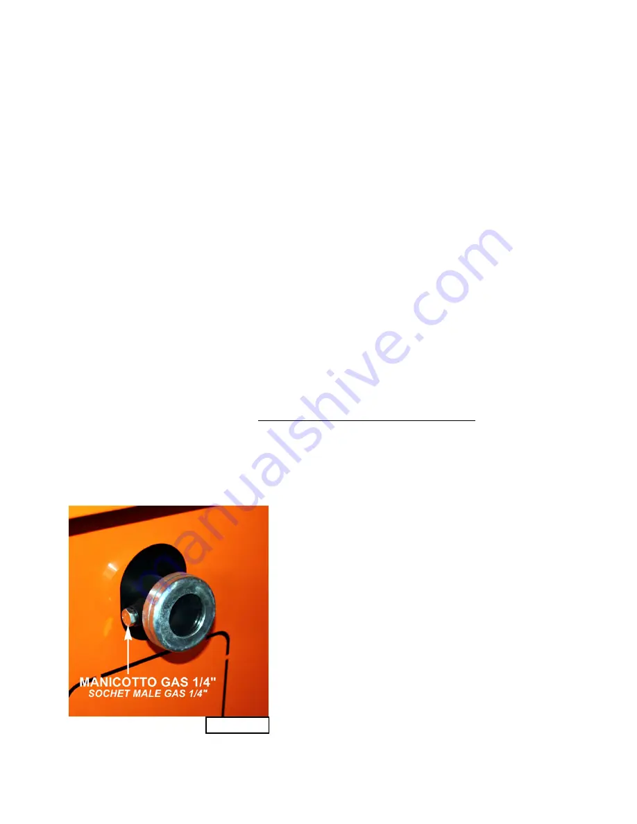
guarantee, with the generator running, a minimum draught of at least –20 Pa (±30%)measured by
applying a connecting nozzle fitting of 1/4” to the sleeve located at the side of the porthole of the
lower door and by introducing a rubber tube connected to a common draught gauge (see
fig.
6.6.1
).
Tab.3.4.1 and tab.3.4.2
indicate the maximum draught values.
In case the necessary draught for functioning is not obtained, we recommend installing an electric
fan at the end of the flue, for forced draught.
6.5 Flue and draught
The flue represents one of the most important elements for the correct functioning of the genera-
tor.
Usually, to obtain a good draught, the flue must be thermally insulated, possibly designed with
double insulated wall to avoid the cooling of the fumes and, therefore, maintain that pressure dif-
ferent enabling the fumes to rise along the chimney pipe up to the external output.
The danger of acid condense, due to the features of the used fuel, recommends the use of stain-
less steel for parts in contact with the fumes. The surrounding structures can influence the correct
functioning of the flue: for example, the distance and height of the adjacent buildings, for which
the regulations in force impose that the end of the flue must exceed by at least 1 m the hipped
roof or of any other construction at a distance of at least 10 m.
An
excessive draught
decreases the generator efficiency: part of the fuel gases together
with fuel parts are sucked in flue before being completely burnt, increasing the consumption
of necessary fuel.
A
scarce draught
decreases the generator efficiency,
in that it slows down combustion,
producing fumes return.
The section of the flue must have the same diameter of the fumes fitting, section shrinking is not admitted.
Furthermore, its weight must not burden on the same fumes fitting to avoid subsidence of the generator
structure
.
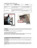
Fig.6.6.3
represents the correct assembly.
fig. 6.6.1


