background image

22

COMMISSIONING – IPS 10 000 | REV. 2.0.0 | © 2021 Dallmeier 

Preparation

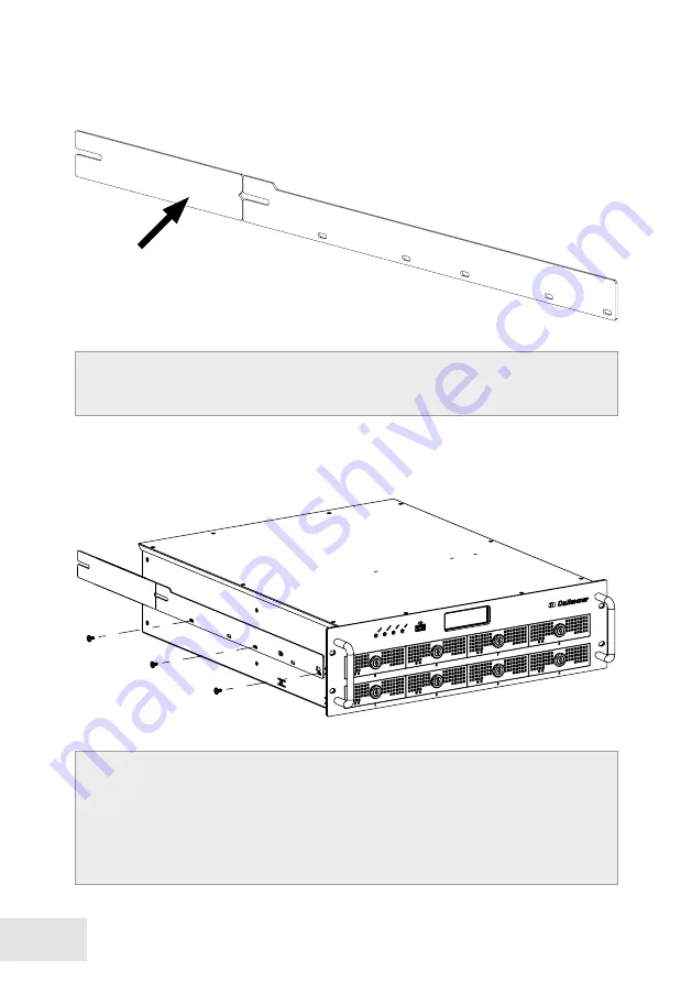
Fig. 1-3

Fig. 1-4


Use the supplied 19” mounting rails.


Shorten the mounting rails if necessary.


Align the guide of the mounting rails to the rear side.


Align the mounting rails according to the depth of the rack.


Fasten the mounting rails to the rack.

Summary of Contents for IPS 10000

Page 1: ...008290 REV 2 0 0 2021 02 18 COMMISSIONING IPS 10000...

Page 2: ...Figures in this document may differ from the actual product Specifications subject to change without notice Errors and misprints excepted All trademarks identified by are registered trademarks of Dal...

Page 3: ...3 COMMISSIONING IPS 10000 REV 2 0 0 2021 Dallmeier 6 32 1 2 2 2...

Page 4: ...4 COMMISSIONING IPS 10000 REV 2 0 0 2021 Dallmeier...

Page 5: ...Safety Instructions 12 6 General Notes 16 Transportation and Packaging 16 Warranty 16 Appropriate Use 16 7 Requirements 17 Power Supply 18 Earthing 19 8 Rack Installation 21 Dimensions 21 Preparation...

Page 6: ...0 2021 Dallmeier 1 Validity This document is valid for the SeMSy Appliance IPS 10000 For simplicity the term appliance or recorder is occasionally used in the following Illustrations in this document...

Page 7: ...ep all documents in a legible condition and in a suitable place for future reference Regularly check the website www dallmeier com for possible updates to the product documentation This Document Commi...

Page 8: ...are SeMSy Recording Server The target group of the document are trained system integrators installers of video security systems Operation SeMSy Recording Server The document Configuration SeMSy Record...

Page 9: ...jury WARNING WARNING indicates a hazardous situation which if not avoided could result in death or serious injury CAUTION CAUTION indicates a hazardous situation which if not avoided could result in m...

Page 10: ...y out instructions for action in the sequence described Expressions in quotation marks usually refer to individual components of the device housing parts mounting elements connections interfaces etc o...

Page 11: ...e limits are designed to provide reasonable protection against harmful interference when the equipment is operated in a commercial environment This equip ment generates uses and can radiate radio freq...

Page 12: ...after repair modification of electrical equipment Periodic testing of electrical equipment General requirements for electrical safety Regulations The use of video and audio surveillance systems is in...

Page 13: ...nctions and damages In this case wait up to 8 hours until the device has reached room temperature be fore commissioning Earthing Equipotential Bonding For the safety of persons protection against dang...

Page 14: ...ing operation Foreign Bodies If objects or liquids get into the device immediately disconnect the mains voltage to the device e g by switching off the circuit breaker associated with the circuit Infor...

Page 15: ...o not dispose of electrical and electronic devices in household waste Disconnect the mains voltage to the device e g by switching off the circuit breaker associated with the circuit Remove all connect...

Page 16: ...inst damage moisture heat and cold Warranty The terms and conditions valid at time the contract was signed shall apply Appropriate Use The IPS 10000 appliance in the MK2 revision combines the recordin...

Page 17: ...with restricted access to equipment room or server room Ensure that the rack is stable and can support the weight of the installed equipment Device Installation Mount heavy equipment in the lower are...

Page 18: ...power supply UPS to protect the device from volt age spikes and to keep it in operation in case of power failure ATTENTION Danger due to difficult separation from the circuit The plug of the supply l...

Page 19: ...res prescribed in accordance with cur rently valid DIN VDE and ISO standards to ensure standard compliant grounding and correct lightning protection equipotential bonding of the device and all connect...

Page 20: ...nd in a de energized state check that no voltage is present Perform all measures prescribed by currently valid DIN VDE and ISO standards to ensure that the device is grounded in accordance with the st...

Page 21: ...ommissioning of the device may only be carried out by trained specialist personnel You will need the following tools accessories for installation Phillips screwdriver 5 mm Torx six head screwdriver T1...

Page 22: ...eparation Fig 1 3 Fig 1 4 Use the supplied 19 mounting rails Shorten the mounting rails if necessary Align the guide of the mounting rails to the rear side Align the mounting rails according to the de...

Page 23: ...23 COMMISSIONING IPS 10000 REV 2 0 0 2021 Dallmeier Installation Fig 1 5 Mount the 19 brackets on the rear side of the rack Make sure that the guides are facing the inside...

Page 24: ...into the guides Push the device completely into the rack Ensure min 10 cm free space at the front and rear Mount the device on the front side of the rack CAUTION Risk of injury due to high weight Make...

Page 25: ...ed for installation by Dallmeier see HDD whitelist on www dallmeier com must not be formatted or partitioned should have the same capacity number of sectors should be from the same production series w...

Page 26: ...000 REV 2 0 0 2021 Dallmeier Fig 1 8 Place the HDD tray on the bottom of the HDD Make sure that the connectors of the HDD are positioned at the back of the HDD slot Make sure that the HDD and HDD tray...

Page 27: ...27 COMMISSIONING IPS 10000 REV 2 0 0 2021 Dallmeier Mount the HDD tray on the HDD with 4 screws Fig 1 9...

Page 28: ...10000 REV 2 0 0 2021 Dallmeier Fig 1 10 Make sure that the HDD slot and the housing are flush Lock the HDD tray with the key Fig 1 11 Insert the HDD tray into the guide rail Carefully slide the HDD t...

Page 29: ...on the number and capacity of the installed hard disks var ious messages and dialogs are displayed during the initial startup and initialization Confirm the messages if necessary Follow the instructi...

Page 30: ...12 A Hard disk 1 3 5 HDD on HDD tray B Power blue Lights up whenever the device is turned on C Record green Indicates the recording activity HDD activity of the device D Alarm orange Lights up when t...

Page 31: ...OK HDD is defective HDD is not active and OK RAID spare HDD HDD is in rebuild process RAID HDD is not installed Fig 1 13 C Line for status messages D E F Status power supply 1 D 2 E and 3 F Power sup...

Page 32: ...60 Hz N USB Interface USB 3 1 Gen 1 type A D Relay OUT 1 4 Weidm ller socket 8 pins max 12 V DC 24 V AC 0 5 A 150 mOhm O USB Interface USB 3 1 Gen 1 type A E Contact IN 1 4 Weidm ller socket 6 pins on...

Page 33: ...ble function N O contact 3 4 Relay 3 Configurable function N O contact 5 6 Relay 2 Configurable function N O contact 7 8 Relay 1 Configurable function N O contact Kontakt IN E Weidmueller 6 Pins Pin A...

Page 34: ...using the Dallmeier Device Manager PService3 software Remote Login In the basic state remote login is possible with the serial number as pass word The rights of the Administrator group are valid The c...

Page 35: ...ace is displayed Fig 1 18 If the Slow Network check box is selected the configuration interface is compressed before transmission for narrowband connections Enter the serial number e g DAX5 12345678 a...

Page 36: ...for configuration 1 HDMI only for configuration 1 DVI only for configuration AUX Line IN 1 3 5 mm phone jack Microphone IN 1 3 5 mm phone jack for intercom license 003801 required Audio OUT 1 3 5 mm p...

Page 37: ...1 2 AES network access control according to IEEE 802 1X Electrical Data Voltage supply 115 230 V AC 5 50 60 Hz Power consumption Max 230 W Thermal output Max 785 BTU h Mechanical Data Dimensions W H...

Page 38: ...ork on the device may only be carried out by qualified personnel and in compliance with the locally applicable reg ulations such as the DIN VDE 0701 0702 series of standards VDE 0701 0702 Testing afte...

Page 39: ...instructions ATTENTION Erroneous display possible when replacing power supply units If a new power supply unit is installed in the recorder the corresponding check box must be activated Otherwise the...

Page 40: ...HEADQUARTERS Dallmeier electronic GmbH Co KG Bahnhofstr 16 93047 Regensburg Germany tel 49 941 8700 0 fax 49 941 8700 180 mail info dallmeier com www dallmeier com...

Reviews: