background image

13

Dallmeier electronic

PView  Station  PVS  IV

3 4 5

6

7 8 9 10

12

13 14

15

16

17

11

18

19

20

21

1 2

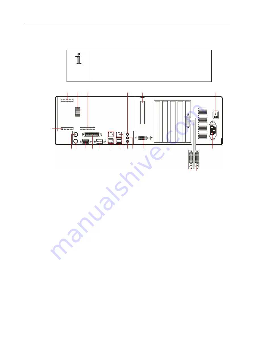
Fig. 5-2

5.2 

Connection assignment

NOTE

The number of connections can differ depending on the ordered 

equipment or device variant.

The following description relates to a standard configuration 

of the PVS IV.

1

  Mouse (PS/2)

2

  Keyboard (PS/2)

3

  Serial interface (9-pin D-SUB, RS232)

4

  Parallel interface (25-pin D-SUB)

5

  M3, VGA output (15-pin D-SUB), inactive


This output will be activated as M1 in case of a PVS IV version without additional VGA 

card. 

6

  2 x RJ45 (inactive)

7

  2 x USB 2.0

8

  LAN port (RJ45)

9

  Mic IN (red) 

10

  Line OUT (green) 

11

   Line IN (blue) 

12

  M4, DVI output (not suitable for VGA adapters), inactive


This output will be activated as M2 in case of a PVS IV version without additional VGA 

card. 

13

  M1, DVI output at breakout cable, lower cable

14

  M2, DVI output at breakout cable, upper cable

15

  Mains connection

16

   Power switch

17

  Eject button for the connection panel

18

  Relais OUT 1 – 5 (inactive)

19

  Temperature sensor for ambient temperature

20

  Contact IN 1 – 24 (inactive)

21

  Contact IN G1 – G6 (inactive)

Summary of Contents for PVS IV

Page 1: ...1 Dallmeier electronic PView Station PVS IV Rev 1 0 0 080528 English Workstation PVS IV Installation and Configuration...

Page 2: ...er accepts no liability for damage to property or pecuniary damages arising due to minor defects of the product or documentation e g print or spelling errors and for those not caused by intention or g...

Page 3: ...Certifications 9 4 Installation and mounting 10 4 1 Requirements at the installation site 10 4 3 Installation in a 19 standard rack 11 5 Views and connection assignment 12 5 1 Front view 12 5 2 Connec...

Page 4: ...configuration of the device General notes on the product and technical data are additionally provided The target audience is exclusively specially trained and authorized professionals instal lers 1 3...

Page 5: ...rect configurations or incorrect actions NOTE ANOTE offers information on principles special features and efficient procedure as well as general recommendations Expression Expressions in bold and ital...

Page 6: ...ded instructions notes and warnings Regulations surveillance systems The use of video and audio surveillance systems is strictly regulated in most countries Therefore inform yourself on laws and regul...

Page 7: ...responsible for your area Do not move while in operation Strong vibrations can cause damage to the unit in particular to the hard disk s Therefore do not bump the unit or move it in a jerky motion wh...

Page 8: ...ntation PVS IV Installation und Konfiguration CD inclusive software documentations The scope of delivery may differ depending on the ordered equipment or device variant The device s range of functions...

Page 9: ...es The PView Station PVS IV is especially characterised by the following functions and pro perties l Operating system Windows XP l DVD R RW writer l 1000 Mbit LAN interface l HDD capacity min 160 GB l...

Page 10: ...direct sunlight l with unsuitable ambient temperatures see technical data l near sources of strong radiation i e X rays radio transmitters or magnetic fields l with corrosive surroundings e g gases o...

Page 11: ...he bracket 2 Pay attention to the case feet that must fit into the notches A 3 Screw together bracket and case from the underside with 3 screws see fig 4 2 1 to 3 4 Mount the PVS IV into the 19 standa...

Page 12: ...PView Station PVS IV 5 Views and connection assignment 5 1 Front view 1 Panel Filter pad 2 Power LED Lights whenever the device is switched on 3 Status LEDs inactive 4 USB 2 0 interface 5 Panel DVD d...

Page 13: ...e This output will be activated as M1 in case of a PVS IV version without additional VGA card 6 2 x RJ45 inactive 7 2 x USB 2 0 8 LAN port RJ45 9 Mic IN red 10 Line OUT green 11 Line IN blue 12 M4 DVI...

Page 14: ...itor have to be connected accordingly to M3 and M4 Variant 1 standard with graphics card l M1 and M2 breakout cable are active l M3 and M4 main board are inactive Variant 2 all four monitor connection...

Page 15: ...esting to enter the serial number will be displayed when the Dallmeier software is starting if the licence dongle is not connected accurately If the dialog to enter the serial number is displayed proc...

Page 16: ...NOTE Note the documentation of the operating system and peripheral devices 7 2 Monitors Open the desktop context menu by right clicking on the desktop Select Properties Select the Settings tab in the...

Page 17: ...ut M1 1 M2 2 M3 3 M4 4 see figure 7 2 To configure other monitors proceed analog as above 7 3 Software The PView PGuard and SmartGUI software is already installed on the PVS IV It finally has to be co...

Page 18: ...er changes is dependent upon the installa tion site and the degree of soiling associated with it In normal office rooms checking every three months is generally suffici ent while a monthly check would...

Page 19: ...ard 1 x 3 5 Exchangeable hard disks optional 1 x 3 5 Internal hard disk optional 1 x 3 5 Max storage capacity 3 x 750 GB Interfaces Video OUT 1 x VGA 1 x DVI Audio Line IN 1 x Audio Line OUT 1 x MIC I...

Page 20: ...20 Dallmeier electronic PView Station PVS IV 9 2 Technichal drawing Unit mm Fig 9 1 130 with feet...

Page 21: ...any is responsible for this declaration Dallmeier electronic GmbH Co KG Cranachweg 1 D 93051 Regensburg The measurements were carried out in accredited laboratories For the evaluation of above mention...

Reviews: