background image

1

Battery voltage display (single voltage 3.6V by flashing a warning, 2-6S automatic recognition)

2

Attitude angle display (P: pitch angle

R: Roll angle)

3

Speed

4

Number of GPS satellites (6 stars over automatically record at home, short press the button to

manually record home)

5

Home direction indicator (square in the middle, the front of the screen that is the direction of

home)

6

The total voyage

7

Distance from home

8

Height

9

Azimuth (home and aircraft line and just north of where the angle, measured clockwise)

10

Head toward (just north of 0 °, calculated clockwise)

11

Remote RSSI signal strength (RSSI output requires Receiver support, not displayed by default)

12

Horizon (coincidence horizon, to facilitate the observation flight attitude)

13: Center of the screen icon (supports three kinds of icons, or off)

14: vertical speed

15: Latitude and longitude (LON: longitude

LAT: latitude

E:East

W:West

S:South

N:North)

16

Flight time (can be cleared by the key or remote control)

17

Maximum flight speed (default is not shown)

18

Maximum line distance (default is not shown)

QOSD data can be customized switch, user can display or close any of the contents, QOSD

interface display position can not be changed but CUSTOM custom interface display position can

be changed

Summary of Contents for QOSD

Page 1: ...well as accelerometer built in complete flight data display it can also be used in car models and ship models Support GPS RSSI signal strength and can control OSD switch and other functions by connecting with receiver Technical Parameters Weight 4 8g Dimension 36 7 19 6MM Sensor Compass barometer gyroscope accelerometer Operating Voltage 6 26V GPS baud rate NEMA 0813 4800 9600 19200 38400 57600 11...

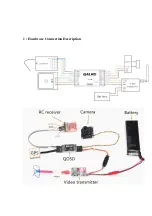
Page 2: ...1 Hardware Connection Description ...

Page 3: ...PS Plug in but positioning failed LED light flashing When positioning success and automatic recorded home or manual recorded LED becomes breathing light 4 Remote control function QOSD support remote connection we recommend using two stage switch control A toggle Open or close OSD data Quick toggle 6 times 3 times back and forth Re recording home position and reset the time Quick toggle 8 times 4 t...

Page 4: ...ard just north of 0 calculated clockwise 11 Remote RSSI signal strength RSSI output requires Receiver support not displayed by default 12 Horizon coincidence horizon to facilitate the observation flight attitude 13 Center of the screen icon supports three kinds of icons or off 14 vertical speed 15 Latitude and longitude LON longitude LAT latitude E East W West S South N North 16 Flight time can be...

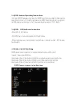
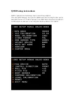
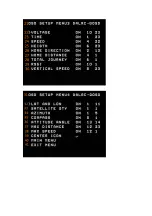
Page 5: ...with very simple set After enter QOSD homepage short press the QOSD board button recording the home position meanwhile clear time to 0 Under the main page press QOSD board button about 2 seconds enter the OSD setup menu short press to next long press about 2 seconds to YES BACK ...

Page 6: ......

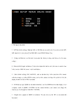
Page 7: ...the receiver RSSI line access click recalibration 5 Video format settings PAL and NTSC such as the discovery of the insertion of the camera without an image or without OSD overlay pull out the camera to change the system can be the display should be PAL or NTSC standard 6 OSD display type QOSD for the default interface such as QOSD interface data display is not complete switch to QOSD1 CUSTOM for ...

Page 8: ...nse the horizon does not coincide or reverse when set generally without setting 16 Boot sereen ON OFF 17 Compass Calibration horizontal rotating clockwise circle then clockwise rotation of the front down the calibration was successful 18 Horizontal calibration the level of the aircraft after entering the automatic calibration automatic exit the calibration the installation is recommended to do a h...

Page 9: ...ent 29 Remote RSSI signal strength display switch position adjustment 30 Vertical speed display switch position adjustment 31 fourth page setup menu MENU CUSTOM 32 Latitude and longitude display switch position adjustment 33 The number of satellites display switch position adjustment 34 Azimuth display switch position adjustment 35 Head direction display switch position adjustment 36 Attitude angl...

Page 10: ...enter of the screen display switch position adjustment 40 Previous Menu 41 Exit menu 42 fifth page of the setup menu CUSTOM MENU submenu 43 Display ON OFF 44 Row from the left count 45 Column start counting from the top 46 SAVE Firmware upgrade Connection method ...

Page 11: ...d upgrade module at the same time in case the insufficient voltage of the upgrade module Select the correct COM number will connect automatically Please upgrade the font file Fonts firstly when upgrading After finish upgrade switch off the power repeat the upgrade mode once again Re upgrade Firmware Firmware After the upgrade completed you must reset the OSD settings ...

Page 12: ...on this model has a complete sensor data for professional players you refer OK Compass POST OK MAG Compass raw data three arrows indicate the data no problem GYRO Gyro raw data DMP Stable posture filtered data ACCE Accelerometer H Altitude PWM Control channel data ...

Reviews: