background image

Linea Lite GigE


Camera User’s Manual


Monochrome CMOS Line Scan 

sensors | 

cameras

 | frame grabbers | processors | software | vision solutions


P/N: 03-032-20294-01 

www.teledynedalsa.com  

Preliminary

Summary of Contents for Everywhereyoulook Linea Lite GigE

Page 1: ...Linea Lite GigE Camera User s Manual Monochrome CMOS Line Scan sensors cameras frame grabbers processors software vision solutions P N 03 032 20294 01 www teledynedalsa com P r e l i m i n a r y ...

Page 2: ...of Microsoft Corporation All other trademarks or intellectual property mentioned herein belong to their respective owners Document date December 7 2020 Document number 03 032 20294 01 About Teledyne DALSA Teledyne DALSA a business unit of Teledyne Digital Imaging Inc is an international high performance semiconductor and electronics company that designs develops manufactures and markets digital im...

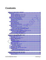
Page 3: ...PTER OVERVIEW 15 Optimizing the Network Adapter used with Linea Lite 15 Optimizing Camera System Performance 15 Power over Ethernet PoE Support 16 GIGE VISION SAPERA APPLICATION DESCRIPTION 17 LINEA LITE GIGE CAMERA QUICK START 18 SAPERA SOFTWARE INSTALLATION 18 Procedure 18 CONECTING THE LINEA LITE GIGE CAMERA 19 Steps for Camera Startup 19 Connectors 20 Powering the Camera 20 Preventing Operatio...

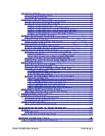
Page 4: ...ients File 40 Important Factors about Flat Field Processing 40 Performing an FFC Setup via Sapera CamExpert 41 Set up Dark and Bright Acquisitions with the Histogram Tool 41 Flat Field Correction Calibration 43 FPN Correction 45 PRNU Correction 46 CAMERA FIRMWARE UPDATES 49 INTERNAL TEST IMAGE GENERATOR 50 Available Test Patterns 50 Grey Horizontal Ramp 50 Grey Vertical Ramp 50 Grey Diagonal Ramp ...

Page 5: ...sferControlMode 84 Features that cannot be changed during a Sapera Transfer 85 EVENT CONTROL CATEGORY 86 Event Control Feature Descriptions 87 Event Info Feature Descriptions 91 Overview of Precision Time Protocol Mode IEEE 1588 92 PTP Master Clock Identity 92 An Example with two Linea Lite Cameras 92 IEEE 1588 Reference Resources 93 Examples using Timestamp Modulo Event for Acquisitions 93 Case E...

Page 6: ...to Nikon F Bayonet Adapter AC LA 00115 A1 R 126 M42x1 to C Mount Adapter AC LC 00001 00 R 127 Lens Image Circle Illustration 128 Additional Lens Parameters application specific 129 OPTICAL CONSIDERATIONS 130 Illumination 130 Light Sources 130 Lens Modeling 131 Magnification and Resolution 131 SENSOR HANDLING INSTRUCTIONS 132 Electrostatic Discharge and the Sensor 132 Protecting Against Dust Oil an...

Page 7: ... is lower than expected 143 Camera is functional line rate is as expected but image is black 143 Other Problems or Issues 144 Buffer Incomplete Error Message 144 Issues with Cognex VisionPro 144 CONTACT INFORMATION 145 SALES INFORMATION 145 TECHNICAL SUPPORT 145 P r e l i m i n a r y ...

Page 8: ... and transfers images between the camera to the host PC GigE with TurboDrive Linea Lite cameras include TurboDrive technology delivering high speed data transfers exceeding the GigE limit TurboDrive uses advanced data modeling to boost data transfers up to 2 or 3 times faster than standard GigE Vision speeds with no loss of image quality These high transfer are achieved using a proprietary process...

Page 9: ... frame Metadata Digital horizontal and vertical binning for increased sensitivity 1µs internal timer or external events can timestamp images Provides 4 User Settings sets to store and recall camera configurations Refer to the Operation Reference and Technical Specifications section of the manual for full details Linea Lite GigE Firmware Teledyne DALSA Linea Lite GigE camera firmware contains open ...

Page 10: ...a free image acquisition and control software development toolkit SDK for Teledyne DALSA S 2D 3D cameras and frame grabbers Hardware independent in nature Sapera LT offers a rich development ecosystem for machine vision OEMs and system integrators Sapera LT includes CamExpert provides an intuitive graphical interface that allows configuring and setup of cameras It includes live image acquisition w...

Page 11: ...est image Internal generator with choice of static patterns User settings Select factory default or either of two user camera configurations Onboard Memory Reserved Packet Resend Buffer 6 MB default user defined feature Reserved Data Buffer 84 MB Total Memory 128 MB Back Focal Distance M42 x 1 mount 12 mm M42 to Nikon F bayonet adapter 46 5 mm 34 5 mm for the F mount adapter plus 12 mm for the cam...

Page 12: ...ance characteristics Limits and methods of measurement EN 61326 1 2013 Electrical equipment for measurement control and laboratory use EMC requirements Part 1 General requirements EN 55024 2010 Information technology equipment Immunity characteristics Limits and methods of measurement CISPR 11 Industrial scientific and medical equipment Radio frequency disturbance characteristics Limits and method...

Page 13: ...z Maximum Line Rate Output System dependent on the GigE network Exposure Control 5 μs to 2500 μs Internal Trigger to Start of Exposure 0 24 μs minimum programmable exposure mode External Trigger to Start of Exposure 0 30 μs minimum programmable exposure mode 0 30 μs pulse width controlled exposure mode Horizontal Line Time 15 6 μs Readout Time 14 44 μs Pixel Size 7 µm x 7 µm Pixel Format User sele...

Page 14: ...verview Linea Lite GigE Series Camera Spectral Responsivity Effective Quantum Efficiency The quantum efficiency graph describes the fraction of photons at each wavelength that contribute charge to the pixel P r e l i m i n a r y ...

Page 15: ... computer to be used with the Linea Lite GigE camera does not have a Gigabit network adapter or second built in Gigabit NIC a Gigabit Network Interface adapter card NIC needs to be installed With any high performance Gigabit NIC adapter review the NIC documentation for any drivers required for the specific host operating system Laptop computers with built in GigE network adapters may not be able t...

Page 16: ...as Linea Lite GigE cameras support the IEEE 802 3x pause frame flow control protocol automatically so images from many cameras can be reliably transmitted through the switch to the NIC efficiently Important The maximum virtual frame rate possible from multiple cameras which are simultaneously triggered will depend on the camera model frame size and network configuration Additionally using Pause Fr...

Page 17: ...the system GigE Vision Transport Layer Control Packet Size The default size of 1500 is often more efficient than larger jumbo packets especially when using Ethernet switches Inter packet Delay Inserts a delay in µs between packets Dependent on the Ethernet connection inserting a short delay even 1 µs can make the difference between transmission errors or no errors at all Device Link Throughput Lim...

Page 18: ...etup requires a powered computer NIC supporting PoE or a PoE capable Ethernet switch or an Ethernet power injector Important Connect power via the I O or PoE not both Although Linea Lite has protection differences in ground levels may cause operational issues or electrical faults If both supplies are connected and active the Linea Lite will use the I O power supply connector Important When using P...

Page 19: ...es a license free development platform for Teledyne DALSA GigE hardware or Sapera vision applications Additionally supported are Sapera GigE Vision applications for third party hardware with the purchase of a GigE Vision Module license or the Sapera processing SDK with a valid license The GigE Vision Compliant XML device description file is embedded within Linea Lite GigE firmware allowing GigE Vi...

Page 20: ... the camera If Linea Lite GigE will be used in a third party GigE Vision Compliant environment Sapera or Sapera runtime is not required follow the installation instructions of the third party package Procedure Download and install Sapera 8 50 which automatically provides GigE Vision support When installing select the installation for GigE Vision support http www teledynedalsa com imaging support d...

Page 21: ...mera is connected The Linea Lite Status LED will change to steady Blue Once communication with the host computer is started the automatic IP configuration sequence will assign an LLA IP address as described in section Linea Lite GigE IP Configuration Sequence or a DHCP IP address if a DHCP server is present on your network The factory defaults for Linea Lite is Persistent IP disabled and DHCP enab...

Page 22: ... connector and LED locations See the Mechanical Specifications section for details on the connectors and camera mounting dimensions Status LED RJ 45 Connector HD15 Connector 1 5 11 15 Powering the Camera Two options are available for powering the Linea Lite GigE camera 1 Power over Ethernet PoE 2 Using a separate power supply connected to the HD15 connector If using PoE for more information refer ...

Page 23: ... platform with a good connection to earth ground Method 4 Avoid running the Ethernet cable close to or parallel to AC power lines GigE Server Verification After a successful Sapera GigE Vision package installation the GigE Server icon is visible in the desktop taskbar tray area note that in Windows 7 the icon remains hidden until a camera is connected After connecting a camera see following sectio...

Page 24: ...ck on Show Status to open a window listing all devices connected to the host system Each GigE device is listed by name along with important information such as the assigned IP address and device MAC address The screen shot below shows a connected Linea Lite GigE with no networking problems In the event that the device is physically connected but the Sapera GigE Server icon is indicating that the c...

Page 25: ...ogress Steady Red Flashing Blue Fatal Error If the camera does not reboot itself contact Technical Support Slow Flashing Blue Ethernet cable disconnected The camera continuously attempts to assign itself an IP address Fast Flashing Blue File Access Feature is transferring data such as a firmware update or FCC transfer and so forth Steady Blue IP address assigned but no application is connected to ...

Page 26: ... automatic device search device discovery Select the Linea Lite GigE device by clicking on the camera icon By default the camera is identified by its serial number The Linea Lite GigE status LED will turn green indicating the CamExpert application is now connected Camera defaults for the following features are AcquisitionLineRate 20000 Hz TriggerMode Off ExposureMode Timed ExposureTime 34 4 ms Cli...

Page 27: ...l frame rates since it generates an interrupt for each virtual video frame the Sapera Grab Demo application is better suited for high frame rates Camera Firmware Updates Firmware is uploaded using the File Access Control features in Sapera CamExpert see the Camera Firmware Updates section P r e l i m i n a r y ...

Page 28: ...em ccf An important component of CamExpert is its live acquisition display window which allows immediate verification of timing or control parameters without the need to run a separate acquisition program Click on any parameter and a short description is displayed below the Category pane The same context sensitive help is available by clicking on the button followed by clicking on a camera configu...

Page 29: ...Sapera acquisition device After a device is selected CamExpert will only present parameters applicable to that device Optionally select a camera file included with the Sapera installation or saved by the user Parameters pane Allows viewing or changing all acquisition parameters supported by the acquisition device CamExpert displays parameters only if those parameters are supported by the installed...

Page 30: ... attribute which defines its requirement or complexity The states vary from Beginner features required for basic operation of the device to Guru optional features required only for complex operations CamExpert presents camera features based on their visibility attribute CamExpert provides quick Visibility level selection via controls below each Category Parameter list Less More The user can also c...

Page 31: ...exposure time equal to the sum of the exposure times for each line Using a TDI array in this manner allows line scan imaging where high speed motion would result in too short an exposure for a single line sensor TDI technology is most useful when signals are very weak since the multiple snapshots of the object are added together to create a stronger signal The object motion must be synchronized wi...

Page 32: ...es modulation transfer function MTF degradation TDI Mode The TDI Mode feature sets the camera s imaging mode The camera has 5 different modes Single Row Mode High Sensitivity Mode Enhanced SNR Mode High Dynamic Range Mode Multi row Sensor Output Mode Single Row Mode Single Row Mode is the default operating mode for the camera The camera outputs 1 line per trigger High Sensitivity Mode In High Sens...

Page 33: ...nput used for synchronizing exposures to external triggers or a programmed function call message by the controlling computer These triggering modes are described below Free running Line or Frame TriggerMode Off The Linea Lite GigE free running mode has programmable internal timers for line rate exposure period and frame rates Line rate and frame rates are independent Frame free running simply mean...

Page 34: ... Trigger Start Starts the acquisition of one line when the acquisition is active Single Frame Trigger Start Starts the acquisition of one frame when the acquisition is active The number of lines in the frame is defined by the Height feature MultiFrame Trigger Start Burst start trigger starts the capture of a number of frames of Height lines No line is lost between frames The number of frames in th...

Page 35: ...nd there will be an associated distortion compression in the scan direction of the image data When the line rate returns to or below the maximum specified then normal imaging will be reestablished Input Line Details The input line signals have the following features for control or status indication Feature Set LineSelector RW LineFormat RW LineMode RW lineDebouncingPeriod RW LineInverter RW LineSt...

Page 36: ...onds in increments of 1 µs The pulse duration can be set from 0 to 16 seconds in increments of 1 µs Example of Free Run Line Mode with Frame Trigger An example setup of free run line acquisition with Frame Trigger and a configurable internal timer is used as follows Set AcquisitionLineRate 20000 Hz Set image Height 100 Select TriggerSelector SingleFrameTrigger Start Set TriggerMode On Select Trigg...

Page 37: ...dividual imaging situations The user can evaluate Gain and Black Level by using CamExpert Features and limitations are described below Black Level offset is expressed as a digital number DN providing a offset from the factory setting The factory setting optimized the black level offset for maximum dynamic range under controlled ideal dark conditions Gain is expressed as a multiplication factor Not...

Page 38: ...l binning is performed over multiple acquisition lines within the camera therefore the virtual frame buffer height is automatically reduced when binning is enabled Note Binning is performed digitally therefore there is no increase in acquisition line rate The following graphic illustrates binning 1 4096 4095 4 3 2 1 2 2048 Horizontal Binning by 2 Line 1 Line 2 Line 3 Line 4 Line 1023 Line 1024 Lin...

Page 39: ... Invert Function LUT Size vs Output Pixel Format The LUT size will be the same as the camera s sensor pixel size for the current Linea Lite standard firmware this is 12 bit All camera processing is performed at the 12 bit sensor pixel format of the camera while the output pixel format is 8 bit or 12 bit A default neutral LUT programming is as follows With Output Pixel format 8 bit the default LUT ...

Page 40: ...ced in value to the minimum allowed the nonlinear output of acquisition data through the LUT effectively boosts low value data As Gamma Correction is increased in value to the maximum allowed the nonlinear output of acquisition data through the LUT effectively reduces low value data DN 0 DN 4095 LUT Output Input DN DN 0 DN 4095 Gamma Factor going to min Gamma Factor going to max Related GigE Visio...

Page 41: ...CalibrationSampleSize flatfieldCalibrationFPN To calibrate PRNU Features flatfieldCorrectionMode flatfieldCalibrationSampleSize flatfieldCalibrationPRNU flatfieldCorrectionAlgorithm flatfieldCorrectionTarget X X To set Back Level offset Features BlackLevel To set Gain Features Gain Flat Field Correction Algorithm Description Flat Field Correction Algorithm Method1 flatfieldCorrectionAlgorithm appl...

Page 42: ... the top half of the new buffer while the gain buffer is in the bottom half A Sapera application saves the new buffer using the SapBuffer class Save function with the format tiff option which allows saving data without loss of significant bits Important Factors about Flat Field Processing Important Before calibration the Linea Lite GigE should be powered on long enough to achieve its nominal tempe...

Page 43: ...o grab a flat light gray image required for calibration Ideally a controlled diffused light source aimed directly at the lens should be used or a non glossy paper with the lens slightly out of focus or evenly lit wall Note the lens iris position for a bright but not saturated image Verify a Dark Acquisition Close the camera lens iris and cover the lens with the lens cap Using CamExpert click on th...

Page 44: ... figure displays a histogram while grabbing a bright gray image Important In this example the average pixel value for the frame is bright gray Note Sensors may show a much higher maximum or lower minimum pixel value due to one or more hot or dead pixels The sensor specification accounts for a small number of hot stuck or dead pixels pixels that do not react to light over the full dynamic range spe...

Page 45: ...tions Note Before performing a FFC Teledyne DALSA recommends evaluating the bare image characteristics which determine the quality of FFC applied to the image A bare image is without gain applied that is all gains are set to 1 To obtain a bare image disable FPN and PRNU coefficients Choose Off from Flat Field Correction Mode Set the Flat Field Correction Mode feature to Off Set the Gain to 1 0 P r...

Page 46: ...d 2 Height An average value near your calibration target is ideal An extremely low output compared to the target will increase noise level significantly after the PRNU is corrected To avoid SNR and or DNR not meeting your application requirements the profile should reach a level near the calibration target Note Changes to gain do not improve image quality from a SNR perspective Gains are analog an...

Page 47: ...tputs are zero then you should adjust the Black Level feature offset value to ensure that all pixel output is above zero Step 3 Set the Flat Field Correction Mode to Calibration and select the required user set from Flat Field Correction Current Active Set drop down menu Step 4 Set the Flat Field Calibration Sample Size feature to 4096 or 2048 The 4096 option returns more accurate results whereas ...

Page 48: ... to Calibration and select the required user set from Flat Field Correction Current Active Set drop down menu Step 3 Adjust the calibration target in the Flat Field Calibration Target in DN if necessary Note 200 DN is commonly used target in 8 bit output format Step 4 Set the Flat Field Calibration Sample Size feature to 4096 or 2048 Step 5 In the Calibrate PRNU feature click Press to perform the ...

Page 49: ...ra Performance and Features 47 Step 8 To load this user set when resetting or powering on the camera use the Power up Configuration dialog Click Setting Power up Configuration feature in Camera Information category P r e l i m i n a r y ...

Page 50: ...e Power up Configuration dialog box select one of four UserSets for both Camera Power up configuration and Load Save configuration and press the Save button This ensures that the camera loads the saved parameters the next time the camera is turned on P r e l i m i n a r y ...

Page 51: ... to upload to the camera File selector choose Firmware Click Browse to open Windows Explorer Select the specific file to Upload Click Upload to Camera to execute the file transfer to the camera When firmware is successfully updated the camera must be reset to effect the change CamExpert displays a dialog indicating that the upload was successful and prompts to reset the camera P r e l i m i n a r ...

Page 52: ...ra processing and Binning functions Use CamExpert to enable and select any test pattern from the Test Image Selector feature drop menu while the camera is not in Acquisition Mode Click Grab to display the pattern output Available Test Patterns Available test patterns include Grey Horizontal Ramp Display is filled with horizontally repeating image ranging from black to white Grey Vertical Ramp Disp...

Page 53: ...hangeable When using CamExpert multiple Linea Lite GigE cameras on the network are seen as different Linea2 2 GigE 4K xxx devices Non Teledyne DALSA cameras are labeled as GigEVision Device Click on a device User Name to select it for control by CamExpert An imaging application uses any one of these attributes to identify a camera its IP address MAC address serial number or User Name Some importan...

Page 54: ... be saved so that they can be restored next time you power up the camera or to protect against losing them in the case of power loss using the User Set Save parameter Once saved the current settings become the selected user set Camera Configuration Selection Dialog CamExpert provides a dialog box which combines the features to select the camera power up state and for the user to save or load a cam...

Page 55: ...t shown In general feature names that start with an uppercase letter are part of the SFNC while those starting with a lowercase letter are part of the DFNC Parameters in gray are read only either always or due to another parameter being disabled Parameters in black are user set in CamExpert or programmable via an imaging application Features listed in the description table but tagged as Invisible ...

Page 56: ...ceVersion Displays the device version This tag will also highlight if the firmware is a beta or custom design RO Beginner Manufacturer part number deviceManufacturerPartNumber Displays extended manufacturer part number information about the device Beginner DFNC Manufacturer Info DeviceManufacturerInfo This feature provides extended manufacturer information about the device such as the firmware des...

Page 57: ...et1 UserSet1 Select the user defined configuration UserSet 1 as the Power up Configuration UserSet2 UserSet2 Select the user defined configuration UserSet 2 as the Power up Configuration UserSet3 UserSet3 Select the user defined configuration UserSet 3 as the Power up Configuration UserSet4 UserSet4 Select the user defined configuration UserSet 4 as the Power up Configuration User Set Selector Use...

Page 58: ...a non volatile memory RW Invisible None None Keep Internal configuration Factory Setting Default Select the Factory Setting values as the Power up Configuration UserSet1 to UserSet4 UserSet1 to UserSet4 Select the user defined configuration as the Power up Configuration DFNC Major Rev deviceDFNCVersionMajor Major revision of Dalsa Feature Naming Convention which was used to create the device s XML...

Page 59: ...n type of the sensor RO Beginner Linescan Linescan 1D line scan sensor Sensor Color Type sensorColorType Defines the camera sensor color type RO Beginner DFNC Monochrome Sensor Monochrome Sensor color type is monochrome Input Pixel Size pixelSizeInput Size of the image input pixels in bits per pixel RO Guru DFNC 12 Bits Pixel Bpp12 Sensor output data path is 12 bits per pixel Sensor Width SensorWi...

Page 60: ...ctual sensor line rate output Beginner DFNC Exposure Mode ExposureMode Sets the operation mode for the camera s exposure Beginner Timed Timed The exposure duration time is set using the Exposure Time feature and the exposure starts with a LineStart event Trigger Width TriggerWidth Uses the width of the trigger signal pulse to control the exposure duration Use the Trigger Activation feature to set ...

Page 61: ...r signals the relationship between an external line trigger and the exposure period as shown in the timing diagrams below is only applicable while the external line trigger does not exceed the maximum allowable line rate Internal Programmable Exposure The Linea Lite GigE in the Internal Programmable Exposure mode has the following features The TriggerSource feature see I O Control Category selects...

Page 62: ...dth Exposure An alternative external trigger mode allows the external signal width to control the exposure duration feature ExposureMode TriggerWidth as illustrated in the following graphic Line readout time remains similar to programmable exposure modes P r e l i m i n a r y ...

Page 63: ...erence 61 I O Control Category The Linea Lite GigE I O controls as shown by CamExpert group features used to configure external inputs and acquisition actions based on those inputs plus camera output signals to other devices P r e l i m i n a r y ...

Page 64: ...tting See Input Signals Electrical Specifications Beginner Line 1 Line1 Select Line 1 and associated I O control block to use as the external trigger source See LineSelector feature for complete list Line 2 Line2 Select Line 2 and associated I O control block to use as the external trigger source See LineSelector feature for complete list Line 3 Line3 Select Line 3 and associated I O control block...

Page 65: ...t The list of supported input line sources is device specific Expert DFNC GND GND Rotary Encoder Input B is not used Line 2 Line2 Line2 is assigned to the Rotary Encoder Input B Rotary Encoder Source Activation rotaryEncoderSrcActivation Specifies the signal edge s use to increment the rotary encoder Expert DFNC Rising Edge RisingEdge The rotary encoder uses the rising edge of the source signal An...

Page 66: ...ion provides details and timing diagrams for the supported trigger modes Beginner DFNC Off Off Line output is Open Software Controlled SoftwareControlled The outputLineValue feature changes the state of the output Pulse on Start of Frame PulseOnStartofFrame Generate a pulse on the start of the Frame Active event Pulse on Start of Line PulseOnStartofLine Generate a pulse on the start of the Line Ac...

Page 67: ... Line1 Line2 Line3 RO Expert Output Line Software Command outputLineSoftwareCmd Writing a value of 1 in the bit field applies the Latch value of the outputLineSoftwareLatchControl and or executes the PulseOnSoftwareCmd for any output line programmed for software control The feature outputLineSoftwareCmd can take any binary value and each bit set to 1 corresponds to a Icommand for an Output Bit 0 i...

Page 68: ... The selected Counter is either Active or Disabled When Disabled the Counter can be configured Expert DFNC Off Off The selected Counter is Disabled Active Active The selected Counter is Enabled Counter Status counterStatus Returns the current state of the counter RO Expert DFNC Counter Idle CounterIdle The counter is idle The CounterStartSource feature is set to off Counter Trigger Wait CounterTri...

Page 69: ...ge AnyEdge Starts counting on the falling or rising edge of the selected Line Counter Incremental Source counterIncrementalSource Select the event source which increments the counter The Event Control section provides details and timing diagrams for the supported events Expert DFNC Off Off Counter is stopped Acquisition Start AcquisitionStart Counts the number of Acquisition Start events Exposure ...

Page 70: ...eset the selected counter Expert DFNC Rising Edge RisingEdge Reset counter on rising edge of the selected signal Falling Edge FallingEdge Reset counter on falling edge of the selected signal Any Edge AnyEdge Reset counter on the falling or rising edge of the selected signal Counter Duration counterDuration Sets the duration or number of events before the CounterEnd event is generated Expert DFNC C...

Page 71: ...the trigger activation mode which starts the timer Expert DFNC Rising Edge RisingEdge Starts counter on rising edge of the selected signal Falling Edge FallingEdge Starts counter on falling edge of the selected signal Any Edge AnyEdge Starts counter on the falling or rising edge of the selected signal Timer Duration in μs timerDuration Sets the duration in microseconds of the timer pulse Expert DF...

Page 72: ...Source Event or CounterEnd the counter is reset to 00 but does not restart counting until the next CounterReset Cmd Example Counter Start Source CounterEnd itself Countermode OFF Counter is IDLE CounterEnd Event Generated Counter is Active CounterStartSource CounterEnd itself Counter Trigger Wait Counter is incrementing Countermode Active Counter Reset CMD Counter Completed CounterResetSource Coun...

Page 73: ...nter Completed CounterResetSource CounterEnd Itself CounterStartSource EVENT and Signal Edge Base CounterResetSource Event Itself 0 Example CounterStartSource Signal Level Base Example 1 Countermode OFF Counter is IDLE CounterEnd Event Generated CounterStartSource Signal Level Base Counter Trigger Wait Counter Register Countermode Active Counter Completed CounterResetSource CounterEnd Itself Count...

Page 74: ...Source Line 1 Counter Trigger Wait Counter Register Countermode Active Counter Completed CounterResetSource CounterEnd Itself CounterStartSource Line Edge Base Example 2 Active Active Active CounterTriggerActivation Falling Edge Counter STATUS 0 12 8 5 10 Any Tick in CounterEventSource Active 1 1 CounterDuration 12 0 The Second StartSource Pulse is ignored P r e l i m i n a r y ...

Page 75: ...ected Lookup Table Expert DFNC User Defined UserDefined Uses the user programmable LUT Gamma Correction GammaCorrection Uses gamma LUT Gamma Correction gammaCorrection Sets the gamma correction factor i e inverse gamma The gamma correction is applied as an exponent to the original pixel value Min 0 001 Max 2 0 Increment 0 001 Expert DFNC LUT Selector LUTSelector Selects which LUT to control and ad...

Page 76: ...ld4 Sets User Flat Field 4 coefficient table as the current Flat Field Flat Field Correction Type flatfieldCorrectionType Specifies the Flat Field correction type Guru DFNC Line Based LineBase Flat field correction is based on an individual line FlatLine Flat Field Correction Algorithm flatfieldCorrectionAlgorithm Specifies the Flat Field correction algorithm to use Guru DFNC Method 1 Method1 The ...

Page 77: ... by flatfieldCalibrationFPN and flatfieldCalibrationPRNU to the active set Expert DFNC Reset Coefficients flatfieldResetCoefficients Reset all FFC coefficients to pass through Expert DFNC Flat Field Correction Pixel X Coordinate flatfieldCorrectionPixelXCoordinate Specifies the X coordinate of the flat field pixel coefficient to access Guru DFNC Flat Field Correction Gain flatfieldCorrectionGain S...

Page 78: ... bit Pixel Size PixelSize Total size in bits of an image pixel Guru 8 Bpp8 8 bits per pixel 12 Bpp12 12 bits per pixel Horizontal Offset OffsetX Horizontal offset from the Sensor Origin to the Area Of Interest in pixels Beginner Width Width Width of the Image provided by the device in pixels The minimum width is 64 pixels and can be specified in increments of 16 pixels Beginner Height Height Heigh...

Page 79: ...signal to noise ratio Binning Horizontal BinningHorizontal Number of horizontal photo sensitive cells to combine together This increases the intensity of the pixels but reduces the horizontal resolution Beginner Binning Vertical BinningVertical Number of vertical photo sensitive cells to combine together This increases the intensity of the pixels but reduces the vertical resolution of the image Be...

Page 80: ...s Display Name Feature Values Description Standard View Metadata Mode ChunkModeActive Activates the inclusion of chunk data metadata in the payload of the image Expert False No chunk data True Chunk data included in payload Chunk Compatibility Mode chunkCompatibilityMode Selects the format of the chunk data metadata in the payload of the image Expert DFNC Sapera LT SaperaLT Metadata compatible wit...

Page 81: ...ring the image acquisition to the metadata attached to the image Counter1ValueAtReset Copies the value of the feature counterValueAtReset at the start of Frame Readout to the Metadata attached to the image Supported only in GenAPI compatibility mode DeviceID Add the DeviceID value to the metadata attached to the image DeviceUserID Add the DeviceUserID value to the metadata attached to the image Te...

Page 82: ...rnatively Sapera LT provides a demo program called GigEMetaDataDemo exe which will grab a number of frames and display the metadata or save it to a file csv In addition source code and C project files are included for a console based executable The following figure shows the Sapera Explorer tool screen with the Metadata Example highlighted Important When an internal test pattern image is selected ...

Page 83: ...Linea Lite GigE Series Camera Operational Reference 81 P r e l i m i n a r y ...

Page 84: ...AcquisitionActive Device is currently doing an acquisition of one or more frames Acquisition Status AcquisitionStatus Reads the state of the internal acquisition signal selected using the AcquisitionStatusSelector feature Expert Acquisition Mode AcquisitionMode Set the acquisition mode of the device It defines the number of frames to capture during an acquisition and the way the acquisition stops ...

Page 85: ...not take bandwidth limitations into account Guru DFNC Transfer Control TransferControlMode Sets the method used to control the transfer Expert Basic Basic Basic mode ensures maximum compatibility but does not allow for control of the transfer flow Transfer Queue Current Block Count transferQueueCurrentBlockCount Returns the current number of blocks in the transfer queue Expert Transfer Queue Memor...

Page 86: ...current frame count in the transfer buffer is displayed in the Value field During live grab if the number of frames in the transfer buffer is increasing then there is a problem with the network or host bandwidth being exceeded Review the Troubleshooting section of this manual and then contact Technical Support for help in reviewing your camera setup Note The ImageLost event occurs when all buffer ...

Page 87: ...SOR CONTROL NA I O CONTROL NA COUNTER AND TIMER CONTROL NA ADVANCED PROCESSING CONTROL flatfieldCorrectionMode IMAGE FORMAT CONTROL PixelFormat OffsetX Width Height BinningHorizontal BinningVertical ACQUISITION AND TRANSFER CONTROL DeviceRegistersStreamingStart DeviceRegistersStreamingEnd EVENT CONTROL NA GIGE VISION TRANSPORT LAYER CONTROL GevSCPSPacketSize GIGE VISION HOST CONTROL InterPacketTim...

Page 88: ...onal Reference Linea Lite GigE Series Camera Event Control Category The Linea Lite GigE Event control as shown by CamExpert groups parameters used to configure Camera Event related features P r e l i m i n a r y ...

Page 89: ...id frame trigger is generated Rejected Frame Trigger InvalidFrameTrigger Event sent on control channel when a frame trigger occurs in an invalid Trigger region The trigger is rejected and no frame acquisition occurs Image Lost ImageLost Event sent on control channel when an image is lost due to insufficient memory Rejected Line Trigger InvalidLineTrigger Event sent on control channel when a line t...

Page 90: ...Resend PacketResend Counts the number of individual packets that are resent Packet Resend Request Dropped PacketResendRequestDropped Counts the number of packet resend requests dropped The camera queues the packet resend requests until they are processed There is a limit to the number of requests that can be queued by the camera When a new request is received and the queue is full the request is d...

Page 91: ...s communication path except for Pdelay_Req Pdelay_Resp Pdelay_Resp_Follow_Up signaling or management messages Master Master The port is behaving as a master port Passive Passive The port shall not place any messages on its communication path except for Pdelay_Req Pdelay_Resp Pdelay_Resp_Follow_Up or signaling messages or management messages that are a required response to another management messag...

Page 92: ...500 μs threshold Threshold_1000 Threshold_1000 1000 μs threshold Threshold_2000 Threshold_2000 2000 μs threshold Timestamp Modulo Event timestampModulo Specifies the additional interval between the current timestamp tick and the event generated This interval has an 80ns accuracy Note that the value zero disables the event generator Expert DFNC Timestamp Modulo Event Frequency timestampModuloFreque...

Page 93: ...o identify the EventInvalidFrameTrigger software Event RO Guru Acquisition Start Next Valid End Data Event ID EventAcquisitionStartNextValid Represents the event ID to identify the EventAcquisitionStartNextValid software Event RO Guru Image Lost Data Event ID EventImageLost Represents the event ID to identify the EventImageLost software Event RO Guru Counter 1 End Event ID EventCounter1End Represe...

Page 94: ...ally changed to IEEE1588 when PTP Mode is enabled This timestamp tick in ns cannot be reset by the user The Linea Lite cameras implement additional features designed to synchronize multiple camera acquisitions via IEEE 1588 PTP Mode not via external camera trigger signals PTP Master Clock Identity The clock ID of the current best master is an Extended Unique Identifier EUI 64 64 bit ID converted f...

Page 95: ...h timestampControlReset if ptpMode Off else only the internal camera Timestamp counter resets Case Examples Overview The following case examples use a simplified Timestamp timeline which for clarity is shown with time tics from 00 to 60 without units A timeline scale based on real time is not required to describe the usage concepts These examples also apply equally to using an internal Timestamp c...

Page 96: ...tTime first event F1 Case 2 differs from case 1 by showing that the period of uncertainty if the start time is near the first modulo count that follows The first frame acquisition may occur at the first modulo count time or at the following The actual value for the uncertainty period may vary between cameras and network conditions 00 10 20 30 40 50 60 Reset Start Time Actual Start Time F1 F2 F3 F4...

Page 97: ...s at 20 The Modulo 10 actual start time for the first acquisition is at Timestamp 30 as described in Case 1 If a new Timestamp reset happens between the Start Time and acquisition Actual Start Time the Timestamp counter will restart from time 00 The Start Time value has already been stored thus the modulo Actual Start Time remains at 30 In this condition the Actual Start Time did not reset 00 10 2...

Page 98: ...ontrolled acquisition A shows the initial conditions with the first acquisition F1 at the actual start time B shows a Timestamp reset occurring after the first acquisition C shows that acquisitions then continue at the first modulo 10 time after the reset due to acquisitions already in progress compared to the example case 3 above 00 10 20 30 40 50 60 Timestamp Reset Start Time Actual Start Time F...

Page 99: ...ualStartTime first event F1 timestampModulo changes to 20 Case 5 shows that the Modulo value can be changed dynamically Using the simple example of case 1 after the second acquisition F2 the Modulo value is changed from 10 to 20 The third acquisition now occurs at modulo 20 time following the previous acquisition 00 10 20 30 40 50 60 Timestamp Reset Start Time Actual Start Time F1 F2 F3 Modulo 20 ...

Page 100: ...e overall throughput Off Off Disables the DeviceLinkThroughputLimit feature On On Enables the DeviceLinkThroughputLimit feature Device Link Throughput Limit in Bps DeviceLinkThroughputLimit Limits the maximum bandwidth of the data that will be streamed out by the device Guru Stream Channel Selector GevStreamChannelSelector Selects the stream channel to control Expert Device Link Speed in Mbps GevL...

Page 101: ...n network interface Guru Primary Application IP Address GevPrimaryApplicationIPAddress Returns the IP address of the device hosting the primary application RO Guru Device Access Privilege Control deviceCCP Controls the device access privilege of an application Guru DFNC Exclusive Access ExclusiveAccess Grants exclusive access to the device to an application No other application can control or moni...

Page 102: ...nterfaces GevNumberOfInterfaces Indicates the number of physical network interfaces supported by this device RO Invisible Message Channel Count GevMessageChannelCount Indicates the number of message channels supported by this device RO Invisible Stream Channel Count GevStreamChannelCount Indicates the number of stream channels supported by this device 0 to 512 RO Invisible Gev Supported Option Sel...

Page 103: ... connected beyond routers The GigE Vision camera is forced a static IP address The NIC IP address must use the same subnet otherwise the camera is not accessible If the camera is connected to a network with a different subnet it cannot be accessed RO Invisible GVCP Extended Status Codes GevGVCPExtendedStatusCodes Enables generation of extended status codes RO Invisible Gev MCP HostPort GevMCPHostP...

Page 104: ...of the selected manifest entry RO Invisible Manifest Secondary URL DeviceManifestSecondaryURL Indicates the second URL to the XML device description file of the selected manifest entry RO Invisible Device Mode Is Big Endian GevDeviceModeIsBigEndian Endianess of the device registers RO Invisible Device Mode CharacterSet GevDeviceModeCharacterSet Character set used by all the strings of the bootstra...

Page 105: ...ing the network configuration for maximum bandwidth Settings for these parameters are highly dependent on the number of cameras connected to a NIC the data rate of each camera and the trigger modes used Information on these features is found in the Teledyne DALSA Network Imaging Module User manual File Access Control Category The File Access control in CamExpert allows the user to quickly upload v...

Page 106: ...ationExecute Read Read Select the Read operation executed by FileOperationExecute Write Write Select the Write operation executed by FileOperationExecute Delete Delete Select the Delete operation executed by FileOperationExecute File Operation Execute FileOperationExecute Executes the operation selected by File Operation Selector on the selected file Guru File Open Mode FileOpenMode Selects the ac...

Page 107: ...ted over FTP DFNC Invisible File Access via the CamExpert Tool Click Setting to open the File Access Control dialog Type select the file type to upload to camera File Selector select the required file different options may be available depending on the Type selected Click Browse to open Windows Explorer and select the specific file to upload Click Upload to Camera to execute the file transfer to t...

Page 108: ...e Registers Streaming End DeviceRegistersStreamingEnd Announces end of registers streaming and performs validation for registers consistency before activating them Invisible Device Feature Streaming Start DeviceFeaturePersistenceStart Announces the start of feature streaming without immediate checking for consistency Invisible Device Feature Streaming End DeviceFeaturePersistenceEnd Announces end ...

Page 109: ... Test on power up and reset after firmware change Image Buffer Accumulation Count Status Image Buffer Memory Size Packet Resend Buffer Memory Size Internal Temperature Reporting In Camera Event Status Flags Invalid External Trigger Image Lost Packet Resend Related Status Ethernet Pause Frame Requested Linea Lite Features for T2IR Monitoring The following table presents some of the Linea Lite camer...

Page 110: ...rigger PulseOnInvalidFrameTrigger Image Transfers Transfer Queue Current Block Count transferQueueCurrentBlockCount Transfer Queue Memory Size transferQueueMemorySize Transferred Image Max Data Size transferMaxBlockSize Transferred Image Min Data Size transferMinBlockSize Transferred Image Average Data Size transferAverageBlockSize Maximum Sustained Frame Rate maxSustainedFrameRate Packet Resend P...

Page 111: ... IP address is obtained typically in a few seconds with Microsoft Windows 7 8 10 If required a persistent IP address can be assigned see the Running the Network Configuration Tool section Preferably a DHCP server is present on the network where the Linea Lite GigE issues a DHCP request for an IP address The DHCP server then provides the IP address The Teledyne DALSA Network Configuration tool inst...

Page 112: ...there are no conflicts with other devices through an arbitration scheme The Windows NIC configuration must be set to DHCP the typical default case and no DHCP server must be present on the network Otherwise an IP address gets assigned by the DHCP server Windows will turn to LLA when no DHCP server answers requests coming from the NIC Windows and Linea Lite GigE are still running the DHCP process i...

Page 113: ...erver for any additional subnet Windows configures a NIC in DHCP mode by default If no DHCP server is present on the subnet Windows reverts to LLA mode Ensure that a different subnet is assigned to each NIC on the network This will automatically be managed correctly when the Teledyne DALSA DHCP server is enabled on one or all subnets used for GigE Vision devices The graphic below illustrates a sys...

Page 114: ...block connecting to the camera Use Teledyne DALSA s Network Configuration tool to recover a camera with an unknown persistent IP It will reset the camera s factory default mode DHCP LLA The camera s MAC address displayed on the exterior camera is required to perform this function For GigE Vision applications the FORCEIP command is used to force a new persistent IP or to change the IP configuration...

Page 115: ...rames The optimal settings will be system dependent These should be optimized for use with the Linea Lite GigE during the installation Refer to the Teledyne DALSA Network Imaging package manual for optimization information Running the Network Configuration Tool The Network Configuration tool provides information and parameter adjustments for network adapters installed in the system and any connect...

Page 116: ...ned PAUSE Frame Support The Linea Lite GigE supports the Gigabit Ethernet PAUSE Frame feature as per IEEE 802 3x PAUSE Frame is the Ethernet flow control mechanism that temporarily stops data transmission on the network The PAUSE Frame feature can help a NIC that does not have enough buffering to handle full speed reception This requires that the flow control option in the NIC property settings an...

Page 117: ...Linea Lite GigE Series Camera Technical Specifications 115 Technical Specifications Mechanical Specifications Linea Lite GigE 4k Linea Lite GigE 4k with M42x1 Lens Mount P r e l i m i n a r y ...

Page 118: ...el Part number Serial number MAC ID 2D Barcode CE logo Made in Canada Statement Additional Mechanical Notes Linea Lite GigE supports a screw lock Ethernet cable see Ruggedized RJ45 Ethernet Cables For information on lens requirements see Lens Selection Overview and Optical Considerations Each camera side has two mounting holes in identical locations which provide good grounding capabilities Overal...

Page 119: ...uction cameras Dimensions x y z are in microns and referenced to the Linea Lite GigE mechanical body or the optical focal plane for the z axis dimension Theta specifies the sensor rotation relative to the sensor s center and camera mechanical Y variance X variance Sensor Alignment Reference Z variance not shown theta variance Linea Lite GigE X variance 300 µm Y variance 300 µm Z variance 300 µm Th...

Page 120: ...ls Ground Signals Ground 6 Line 3 In Out Configurable 2 IO Port 3 7 Line 3 In Out Configurable 2 IO Port 3 8 Future Use NA Reserved for Future Use 9 Future Use NA Reserved for Future Use 10 PWR GND Camera Power Ground 11 Line 4 Out Configurable 3 Output Port 4 12 Line 4 Out Configurable 3 Output Port 4 13 Line 5 NA Configurable 3 Output Port 5 14 Line 5 NA Configurable 3 Output Port 5 15 PWR VCC C...

Page 121: ...ons 119 Mating GPIO Cable Assembly Teledyne DALSA optionally provides for purchase a GPIO breakout cable HD15 Male to 26 Pos Euro Block as shown in the following drawing Use accessory number AC CA 00002 00 R when placing your order P r e l i m i n a r y ...

Page 122: ...mable and is always enabled However RS 422 internal termination will be programmable on lines 1 and 2 in the planned final camera release model Single ended input not available for alpha consignment units However a single ended frame trigger input is planned for the final camera release model The input signals can be used as trigger acquisition event counter or timestamp event or integration contr...

Page 123: ...gh High to Low 3 3 V TTL 1 5 V 1 5 V 5 0 V TTL 2 5 V 2 5 V 12 V 6 V 6 V 24 V 11 V 11 V External Input Timing Reference Input Level Standard Maximum Input Frequency Minimum Pulse Width Source Current Requirements Maximum Signal Propagation Delay at 60 C Input Signal Direction LVTTL 3 3V 20 MHz 25 ns 0 to 3 3 V 100ns 3 3 V to 0 100ns TTL 5 0V 20 MHz 25 ns 0 to 5 V 100ns 5 V to 0 100ns 12V 20 MHz 25 ...

Page 124: ...External Output Signal Single Ended Logic Drive 3 3V TTL OUTPUT not connected OUTPUT Output Enable Output Signal OUTPUT PIN 5 Signal Ground Output Enable External Output Signal Single Ended Logic Drive Mode 5V TTL 12V 24V OUTPUT not connected Output Signal OUTPUT PIN 5 Signal Ground Output Enable External Output Signal User Supplied Pull up Resister and Voltage Reference P r e l i m i n a r y ...

Page 125: ...e should be calculated accordingly Outputs are open disabled on power up with the default factory settings A software reset will not reset the outputs to the open state if the outputs are active A user setup configured to load on boot will not reset the outputs to the open state if the outputs are active The output signals are designed to prevent an output signal glitch on power up or polarity rev...

Page 126: ...124 Technical Specifications Linea Lite GigE Series Camera EC FCC Declarations of Conformity Pending P r e l i m i n a r y ...

Page 127: ... for available lens adapters is provided The first two lens parameters Lens Mount and Lens Image Circle are based on correctly matching the lens to the sensor Brief information on other lens parameters to consider follows those sections Lens Mount Types Linea Lite GigE 4k Linea Lite GigE 4k cameras use a M42x1 lens screw mount and optionally has adapters for F mount AC LA 00115 A1 R and C mount AC...

Page 128: ...126 Additional Reference Information Linea Lite GigE Series Camera M42x1 to Nikon F Bayonet Adapter AC LA 00115 A1 R Nikon F Bayonet to M42x1 Adapter 12mm BFD HEAVY DUTY w clip P r e l i m i n a r y ...

Page 129: ...Linea Lite GigE Series Camera Additional Reference Information 127 M42x1 to C Mount Adapter AC LC 00001 00 R M42 to C Mount Adapter 12mm BFD P r e l i m i n a r y ...

Page 130: ...tes the Linea Lite GigE 4k active sensor relative to the lens image circle It compares the Linea Lite GigE 4k relative to a Nikon FDX lens using the optional F mount adapter Image Circle approximate for Nikon FDX Lens DX format sensor 24x16 mm Linea2 GigE 4k sensor 28 672 mm M42 x 1 Inner Diameter 41mm P r e l i m i n a r y ...

Page 131: ...at some limited distance range at some positive or negative magnification This defines the field of view F Number aperture The lens aperture defines the amount of light that can pass Lenses may have fixed or variable apertures Additionally the lens aperture affects Depth of Field which defines the distance range which is in focus when the lens is focus at some specific distance Image Resolution an...

Page 132: ...Technology Primers Exposure settings have more effect than illumination The total amount of energy which is related to the total number of photons reaching the sensor is more important than the rate at which it arrives Example 5 J cm2 can be achieved by exposing 5 mW cm2 for 1ms just the same as exposing an intensity of 5 W cm2 for 1 s Light Sources Keep these guidelines in mind when selecting and...

Page 133: ...ens surface to the second focal point The object distance OD is the distance from the first principal point to the object Primary Points in a Lens System Magnification and Resolution The magnification of a lens is the ratio of the image size to the object size h h m Where m is the magnification h is the image height pixel size and h is the object height desired object resolution size By similar tr...

Page 134: ... 24 hours Protecting Against Dust Oil and Scratches The sensor window is part of the optical path and must be handled with extreme care Dust can obscure pixels producing dark patches on the sensor image Dust is most visible when the illumination is collimated The dark patches shift position as the angle of illumination changes Dust is normally not visible when the sensor is positioned at the exit ...

Page 135: ...f air while moving the camera in the air stream Agitating the container will cause condensation to form in the air stream Note Extended airbursts will chill the sensor window causing more condensation Condensation when left to dry naturally will deposit particles on the sensor Use lint free ESD safe cloth wipers The Anticon Gold 9 x 9 wiper made by Milliken is both ESD safe and suitable for class ...

Page 136: ... cable is recommended in a high vibration environment All cables made in U S A all cables RoHS compliant CAT6 certified tested for near end far end crosstalk and return loss IGE 3M 3meters IGE 10M 10meters IGE 25M 25meters IGE 50M 50meters IGE 100M 100meters For Information contact Components Express Inc CEI 10330 Argonne Woods Drive Suite 100 Woodridge IL 60517 4995 Phone 630 257 0605 800 578 669...

Page 137: ...The camera has obtained an IP address and there are no network issues Optimization may still be required to maximize performance Problem Type Summary Camera problems are either installation or setup related where the camera is found but not controllable Additionally the camera may be properly installed but network optimization is required for maximum performance Device Not Available A red X over t...

Page 138: ...vers modify the NIC properties such that the Teledyne DALSA Sapera Network Imaging Driver does not install Verify such a case by uninstalling the third party driver and installing the Linea Lite GigE package again Verify that your NIC is running the latest driver available from the manufacturer Device Available but with Operational Issues A properly installed Linea Lite GigE with no network issues...

Page 139: ...uld be included with the request for support From the Start menu go to Programs Dalsa Sapera LT Tools and run the Log Viewer program From its File menu click on Save Messages to generate a log text file Report the version of GigE Vision software and Sapera version used Installation Issues and Functional Problems This section covers issues that are apparent after installation or are indicated by th...

Page 140: ...r tray icon is displaying a warning Open the Teledyne DALSA s Network Configuration Tool from Window s Start Menu Cameras displayed in red require a NIC IP Click the camera name and Select Device IP Configuration tab Note The network tool provides a Scan Network button if no cameras are displayed P r e l i m i n a r y ...

Page 141: ...Linea Lite GigE Series Camera Troubleshooting 139 Click Automatic Recovery Force IP P r e l i m i n a r y ...

Page 142: ...avoid this issue assign a persistent IP address to the camera Click the Persistent IP Mode shown above and press the Apply button to assign the IP address It will automatically connect to the host PC if the IP address does not conflict with other network IP addresses See Persistent IP section for more information Note Assigning two devices the same IP Address will cause conflicts P r e l i m i n a...

Page 143: ...is found by the Sapera GigE Server but an application such as CamExpert does not see the camera A Linea Lite GigE that had a fault with a firmware update will automatically recover by booting with the previous firmware version Important New cameras installed in previously deployed systems are fully backward compatible with the older vision application Power Failure During a Firmware Update Now Wha...

Page 144: ...ite GigE is in a high vibration environment See Ruggedized RJ45 Ethernet Cables Check the Ethernet status LEDs on the Linea Lite GigE RJ45 connector The Link Status indicator is on and the activity LED should flash with network messages Verify that the Ethernet cable is CAT5e or CAT6 This is very important with long cable lengths When using very long cables up to the maximum specified length of 10...

Page 145: ...hile running CamExpert and grabbing in free run mode at the maximum frame rate start the Sapera Monitor tool from the Sapera Tools installed with Sapera Make sure the Memory Overflow event monitor is enabled Continue grabbing at maximum frame rate If any memory overflow events are counted the internal buffer could not be transmitted on time and was discarded Such a condition may occur at high fram...

Page 146: ... line rate x frame buffer height than the time set for the GigE Vision Host Control Increase the Image Timeout value as required Issues with Cognex VisionPro When the Cognex VisionPro package is uninstalled the Linea Lite GigE becomes not available within CamExpert due to the Cognex uninstaller removing GigE Vision components This forces the user to reinstall the camera package Cognex VisionPro re...

Page 147: ...eledyne DALSA GMBH Lise Meitner Str 7 82152 Krailling Munich Germany Tel 49 89 89545730 sales europe teledynedalsa com Asian Pacific Sales Teledyne DALSA Asia Pacific Ikebukuro East 6F 3 4 3 Higashi Ikebukuro Toshima ku Tokyo Japan Tel 81 3 5960 6353 Fax 81 3 5960 6354 sales asia teledynedalsa com Teledyne DALSA Asia Pacific Room 904 Block C Poly West Bund Center 75 Rui Ping Road Shanghai 200032 T...

Reviews: