•
95
Appendix A: Camera Link
Output Signals, Camera Link Clocking Signals
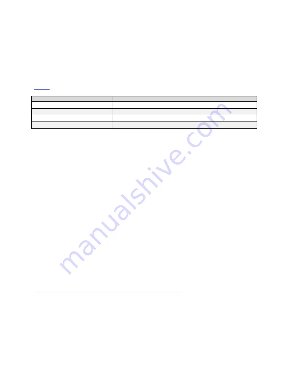
These signals indicate when data is valid, allowing you to clock the data from the camera to
your acquisition system. These signals are part of the Camera Link configuration and you
should refer to the Camera Link Implementation Road Map, available at our
Knowledge
Center
, for the standard location of these signals.
Clocking Signal
Indicates
LVAL (high)
Outputting valid line
DVAL
Not used, stuck low
STROBE (rising edge)
Valid data
FVAL (high)
Outputting valid frame
The sensor internally digitizes to 10, 9, or 8 bits. The camera outputs the 8 most significant
bits (MSB’s) or all 10-bits depending on the Camera Link mode that the camera is
operating in.
Camera Link cable quality and length
The maximum allowable Camera Link cable length depends on the quality of the cable used
and the Camera Link strobe frequency. Cable quality degrades over time as the cable is
flexed. In addition, as the Camera Link strobe frequency is increased the maximum
allowable cable length will decrease.
The cameras are capable of driving cables less than 7 metres in length. We do not
guarantee good imaging performance with low quality cables of
any
length. In general, we
recommend the use of high quality cables for any cable length.
Recommended Cables
We recommend the use of high-quality mini-CL cables. Teledyne DALSA has 3 meter and 5
meter cables available as accessories. Contact Customer Support.
Data Connector: Camera Link
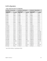
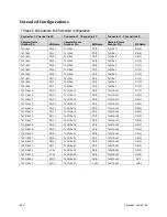
The camera uses two mini-Camera Link SDR-26 cables transmitting the Camera Link Full or
Extended configuration. The figure below shows the SDR-26 mini Camera Link Connector
and the tables that follow list the Camera Link Full and Extended configurations.
For detailed information on Camera Link please refer to the Camera Link Road Map available
from the Knowledge Center on the Teledyne DALSA Web site:
(
http://www.teledynedalsa.com/mv/knowledge/appnotes.aspx
).

