Linea ML Color Cameras
The Linea ML Color Camera
21
Setting Up for Imaging
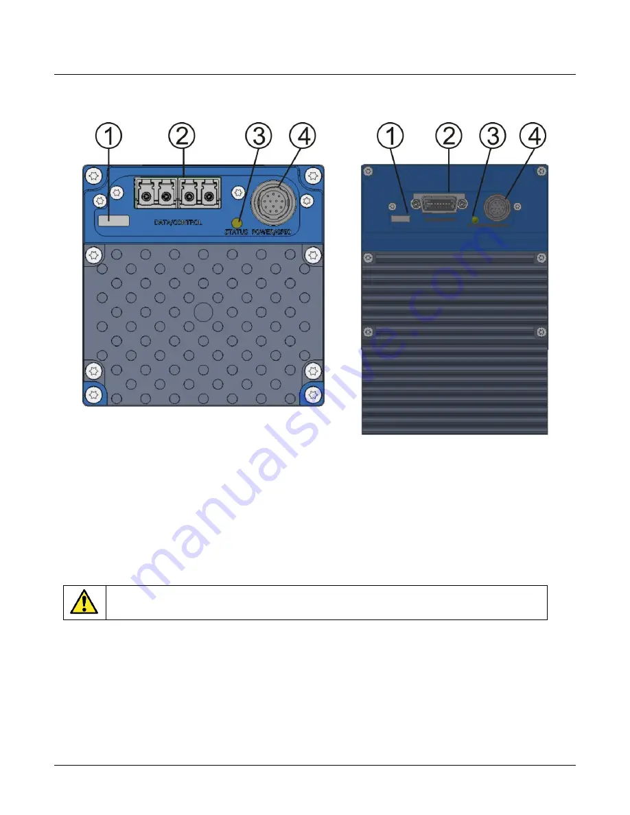
Figure 8. Camera I / O Connectors: 8K FC (left) & 16K HC (right)
Camera I / O Connectors
1) Factory use only.
2) Data and control connectors: LC (ML-FC) and CX4 (ML-HC).
3) LED status indicators.
4) Power and GPIO connectors: +12 V to +24 V DC, Hirose 12-pin circular.
Powering the Camera
WARNING: When setting up the camera’s power supply follow these guidelines:
Apply the appropriate voltages of b12 V to +24 V. Incorrect voltages may damage
the camera.
Before connecting power to the camera, test all power supplies.
Protect the camera with a 3-amp slow blow fuse between the power supply and the camera.
Do not use the shield on a multi-conductor cable for ground.
Keep leads as short as possible to reduce voltage drop.
Use high quality supplies to minimize noise.
Summary of Contents for ML Series
Page 16: ...14 The Linea ML Color Camera Linea ML Color Cameras Mechanical Drawings ML FC 08K10T 00 R ...
Page 17: ...Linea ML Color Cameras The Linea ML Color Camera 15 ML FC 16K04T 00 R ...
Page 18: ...16 The Linea ML Color Camera Linea ML Color Cameras ML HC 16K10T 00 R ...
Page 80: ...78 Declaration of Conformity Linea ML Color Cameras Declaration of Conformity ...


