Spyder 3 CL User's Manual
PRELIMINARY
55
DALSA
03-032-20008-03
7.5 Analog and Digital Signal Processing Chain
Processing Chain Overview and Description
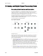
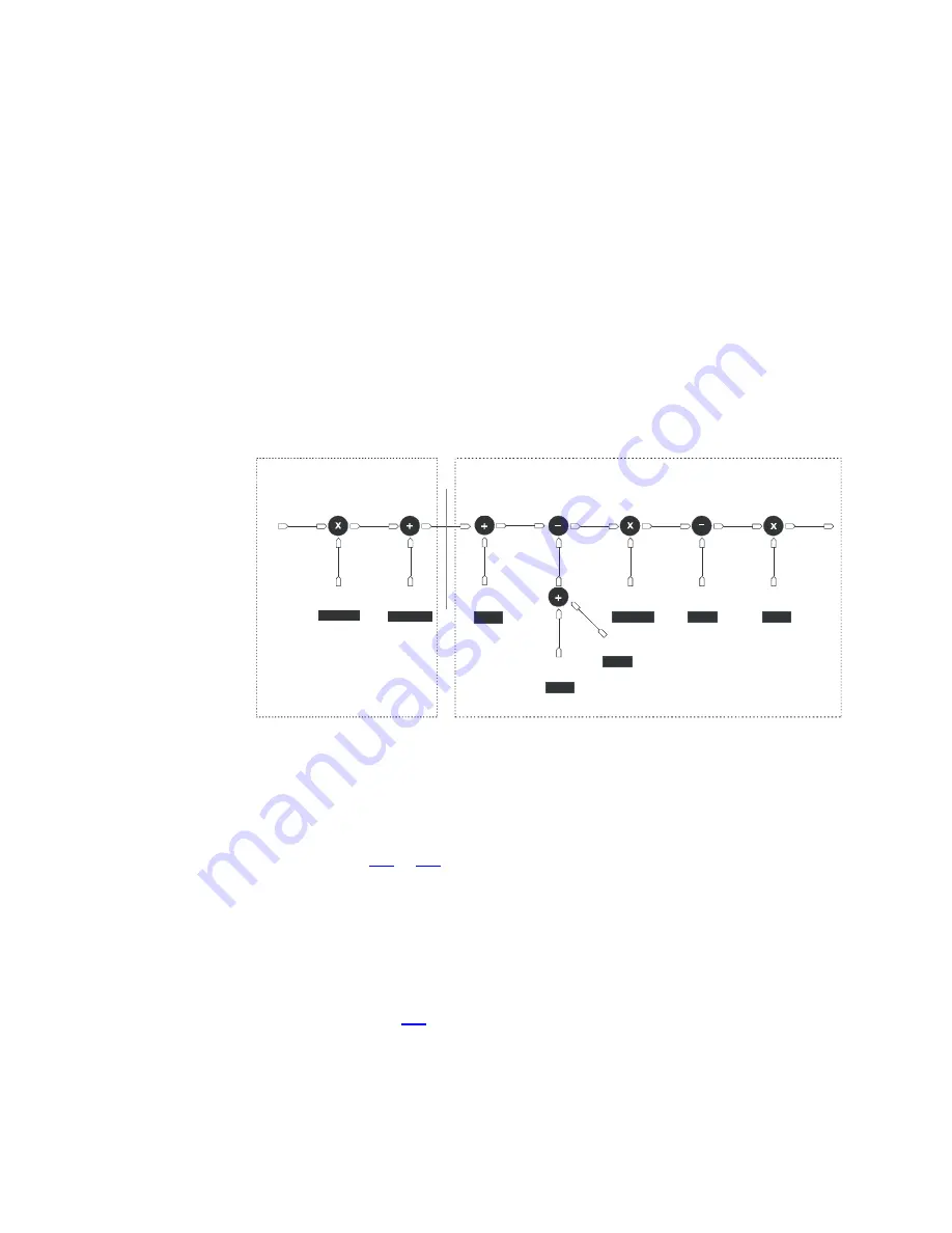
The following diagram shows a simplified block diagram of the camera’s analog and
digital processing chain. The analog processing chain begins with an analog gain
adjustment, followed by an analog offset adjustment. These adjustments are applied to
the video analog signal prior to its digitization by an A/D converter.
The digital processing chain contains the FPN correction, the PRNU correction, the
background subtract, and the digital gain and offset. Non-linearity look-up table (LUT)
correction is available for the 4k model of camera.
All of these elements are user programmable.
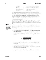
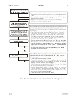
Figure 27: Signal Processing Chain
Analog Processing
Digital Processing
analog
video
analog
gain
analog
offset
FPN
coefficients
digital
offset
PRNU
coefficients
background
subtract
digital
system
gain
sag,ccg
sao
ccf
sdo
ccp,cpa
ssb
ssg
eil
LUT
addition
4k
ONLY
Analog Processing
Optimizing offset performance and gain in the analog domain allows you to achieve a
better signal-to-noise ratio and dynamic range than you would achieve by trying to
optimize the offset in the digital domain. As a result, perform all analog adjustments
prior to any digital adjustments.
1.
Analog gain (
sag
or
ccg
command.) is multiplied by the analog signal to increase the
signal strength before the A/D conversion. It is used to take advantage of the full
dynamic range of the A/D converter. For example, in a low light situation the
brightest part of the image may be consistently coming in at only 50% of the DN. An
analog gain of 6 dB (2x) will ensure full use of the dynamic range of the A/D
converter. Of course the noise is also increased. Note: To maintain valid LUT
calibration do not use the
sag
command with the 4k model. Instead, use the
ssg
command.
2.
The analog offset (
sao
command) or black level is an “artificial” offset introduced
into the video path to ensure that the A/D is functioning properly. The analog offset
should be set so that it is at least 3 times the rms noise value at the current gain.
Summary of Contents for Spyder 3 S3-10-01k40-00-R
Page 22: ...22 PRELIMINARY Spyder 3 CL User s Manual 03 032 20008 03 DALSA ...
Page 30: ...30 PRELIMINARY Spyder 3 CL User s Manual 03 032 20008 03 DALSA ...
Page 42: ...42 PRELIMINARY Spyder 3 CL User s Manual 03 032 20008 03 DALSA ...
Page 104: ...104 PRELIMINARY Spyder 3 CL User s Manual 03 032 20008 03 DALSA ...
Page 112: ...112 PRELIMINARY Spyder 3 CL User s Manual 03 032 20008 03 DALSA ...
Page 114: ...114 PRELIMINARY Spyder 3 CL User s Manual 03 032 20008 03 DALSA ...

