background image

24 

The cameras will be seen in Sherlock in the same order as they appear in the Sapera 
Acquisition Wizard. If the order is not to your liking, there are two ways you can correct 
this. 
 

1.Exit the wizard, disconnect the cameras, and reconnect them in the order you desire. 
Use the SHOW Status Dialog Box (located in the windows tray at the bottom of your 
display) to monitor when the cameras are recognized. Open the Sapera Acquisition 
Wizard and create a new file following the steps above. 

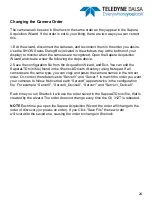
2.Save the configuration file from the Acquisition Wizard, and Exit. You can edit the 
SaperaLTDrv.ini file (found in the Sherlock\Drivers directory) using Notepad. If all 
cameras are the same type, you can copy and paste the camera names in the correct 
order. Or, correct the references to “Server0” and “Server1” to match the order you want 
your cameras to follow. Notice that each “Server#” appears twice in the configuration 
file. For example, “Server0”, “Server0_Device0”, “Server1” and “Server1_Device0”. 

 
Each time you run Sherlock it will use the order saved in the SaperaLTDrv.ini file, that is 
created by the wizard. The order does not change every time the GV 312T is rebooted. 

 
NOTE

 Each time you open the Sapera Acquisition Wizard, the order will change to the 

order of discovery (or power-on order). If you Click “Save File” the new order 
will overwrite the saved one, causing the order to change in Sherlock. 

Changing the Camera Order 

Summary of Contents for Touch GEVA GV-312T

Page 1: ...GV 312T Touch Series GEVA Vision System Installation Manual 405 00046 00 September 9 2014 Revision 1 1 ...

Page 2: ...art of this manual and the related documentation are prohibited except with the express written consent of Teledyne DALSA Incorporated The information in this document is subject to change without notice Teledyne DALSA Incorporated makes no representations or warranties with respect to the contents of this manual and specifically disclaims any implied warranties of merchantability or fitness for a...

Page 3: ... shielded cables are used for external wiring A certificate of compliance is available upon request FCC This product has been tested and found to comply with the limits for a class A digital device pursuant to Part 15 of the FCC rules These limits are designed to provide reasonable protection against harmful interference in a residential installation This equipment generates uses and can radiate r...

Page 4: ...al electronics to a potentially hazardous environment by opening the enclosure Doing so may cause serious damage User Service Warning With the exception of the externally accessible CFAST solid state drive this product has no field replaceable component Tampering with the unit will void the product warranty Warranty Teledyne DALSA warrants the GV 312T against defects in materials and workmanship f...

Page 5: ...USB 14 Typical Configuration not using the PL USB 15 Software Getting Started 16 Directory Structure 16 The License Manager 17 iNspect Express Setup 18 Camera Selector 19 iDiscover 20 Sherlock Setup 21 Sapera CamExpert 22 Sapera Acquisition Wizard 23 Changing Camera Order 24 Enhanced Write Filter 25 Specifications GV 312T Specifications 26 Mechanical Drawings 27 Appendix A Touch Screen Calibration...

Page 6: ...on of inspection solutions without requiring an external PC Runtime monitoring of inspections operator interface Runtime tool parameter editing Offline solution debugging using built in emulation The GV 312T system utilizes a dual core processor running the Windows 7 Embedded operating system As such users have the option of developing their own custom operator interface instead of using the pre i...

Page 7: ...ct Express software 03 Sherlock software 04 Standard components ship with every GV 312T Component Description A VESA T VESA mounting hardware A PWR 24 DIN mountable 24VDC power supply A CAM XXXXXX XX Genie GigE cameras A CAB GE X Ethernet cables A CAB GEVA FX GEVA I O cables A PL USB USB I O breakout module Optional components Partial listing shown Product Support This manual will assist you with ...

Page 8: ...er interface controls connections and mounting holes 1 2 3 Front View 1 Reset button front accessible USB port 2 12 Touch LCD display refer to appendix A for touch screen calibration 3 Press control function keys as follows 2 ...

Page 9: ...network adapter change settings interface Marking Default IP Connection LAN1 Dynamic IP Address DHCP enabled LAN network LAN2 Static IP Address 192 168 11 1 Camera Port 1 LAN left LED Off 10 Mbits s GREEN 100 Mbits s ORANGE 1000 Mbits s LAN right LED ON port active BLINK port traffic Jumbo frames enabled on Camera Port not enabled on LAN1 port NOTE Genie Ethernet cables must be type Cat5 or Cat5e ...

Page 10: ...10 Installation Mount the Unit Panel Mount Locate the panel mounting clips included with the product Put the clamps into the holes located on the sides of the product as shown ...

Page 11: ... gasket included in the mounting kit around the inside back lip of the panel Place the GV 312T into the correct sized cutout on a control panel or frame and tightly screw the panel mounting clamps around the edges to secure the product ...

Page 12: ...atible ARM This requires an optional mounting bracket A VESA T that should be purchased with the unit Take the bracket assembly and attach it to the back and sides of the product as shown below Make sure not to cover the door of the CFAST flash drive A VESA T CFAST Door Left side assembly Right side assembly ...

Page 13: ...t with your Teledyne DALSA representative on applications requiring more than 4 cameras or high inspection speeds iNspect Express and Sherlock use different software drivers to interface GigE cameras iNspect Express uses a driver called IFC whereas Sherlock uses one called Sapera LT The setups associated with each will be described later in the manual Generally Sapera offers additional flexibility...

Page 14: ...OTES 1 Power connections not shown 2 Use A CAB GE X for camera Ethernet connections 3 Use A CAB GEVA FX for I O connections between camera and PL USB Setup Operator HMI iNspect Express shown Camera Network I O Connections USB LAN2 PL USB GV 312T Switch ...

Page 15: ...t the PL USB module NOTES 1 Power connections not shown 2 Use A CAB GE X for camera Ethernet connections 3 Use A CAB GTP FX cables for camera power Setup Operator HMI Sherlock shown Camera Network I O Connections LAN2 GV 312T Switch ...

Page 16: ...t Express C Program Files Teledyne Dalsa iNspect Express for VA Express bat iNspect Express Solution Files C Users Teledyne AppData Local Teledyne Dalsa iNspectExpressVA Solutions iNspect Express Emulator Images C Users Teledyne AppData Local Teledyne Dalsa iNspectExpressVA Images iDiscover C Program Files Teledyne Dalsa iNspect Express for VA iDiscoverGenie exe License Manager C Program Files Tel...

Page 17: ...se matches what you ordered before going any further Open the license manager from the start menu as follows Start All Programs Teledyne DALSA iNspect Express for VA License Manager OR Start All Programs Teledyne DALSA Sherlock License Manager If the license does not reflect what you purchased consult your Teledyne DALSA sales representative The license is field upgradable by entering a new string...

Page 18: ...nse Manager 3 Open the Camera and Language Selector Program from shortcut and configure preferences Select GigE in the camera menu 4 Click on the iDiscover button to detect and configure cameras connected to the system 5 Save Camera set select which connected cameras you want to use 6 Close iDiscover and launch iNspect Express run panel shown below iNspect Express Setup ...

Page 19: ...features for your application These features are peculiar to the iNspect Express software and are detailed in the software users manual From the camera selector tool you can launch both iDiscover and iNspect Express as shown below To launch the emulator simply select the Virtual DEMO Camera The Camera and Language Selector Click to launch iDiscover Click to launch iNspect Express ...

Page 20: ...ort IP segment at the top Click the Apply button to save changes Note Conflicting IP addresses will be designated by a red camera icon in the detected camera menu Select cameras to use in your iNspect Express configuration by clicking and moving them to the left panel using the arrow buttons You can change the camera order by using the up down arrow buttons on the left control bar Save the correct...

Page 21: ...re cameras connected to the system icon shortcut on the desktop 4 Run the Sapera CamExpert utility if you want to change settings in any of the cameras such as exposure strobe or white balance 5 Run the Sapera Acquisition Wizard Verify cameras are shown as expected and save the configuration file SaperaLTDrv ini by clicking the save button 6 Launch Sherlock via shortcut on the desktop Sherlock GUI...

Page 22: ...ing the Sapera CamExpert utility You can configure the camera to load either your saved settings or the factory settings at power up The preferred method is to save your settings to both the camera and a configuration file Sherlock can load a configuration file at startup If multiple configurations are needed you can save them to different camera configuration files Some example configuration file...

Page 23: ...l not run saved programs Instead Sherlock will open a new investigation solution file The Sherlock application uses the settings stored in the camera or in camera configuration files You can also use Sherlock instructions to change Gain Exposure shutter time or Strobe pulse width IO Camera SetNumberFeature programmatically When you launch the wizard you will see the dialog below All cameras connec...

Page 24: ...n the Sherlock Drivers directory using Notepad If all cameras are the same type you can copy and paste the camera names in the correct order Or correct the references to Server0 and Server1 to match the order you want your cameras to follow Notice that each Server appears twice in the configuration file For example Server0 Server0_Device0 Server1 and Server1_Device0 Each time you run Sherlock it w...

Page 25: ... AppData directory will be allowed all other system and program directories will be blocked The EWF is located in the C IPD Install Files directory The procedure to enable the filter is as follows 1 Browse to the C IPD Install Files directory 2 Right click on the file enable_filter7 bat and select run as administrator To disable the filter default state do the following 1 Browse to the C IPD insta...

Page 26: ...x USB 2 0 1 front and 4 bottom I O Supported through PL USB module LED status 1 for Power Display TFT LCD 5 wire analog resistive XGA 16 2M colors Power 24V 60W Via screw terminal header on bottom Cooling Fanless Passive heatsink Mechanical Material Aluminum with paint finish Mounting Panel or VESA option specified at time of order Size 325 x 44 x 259 mm Weight 2 2KG Environment Temp 0 C to 50 C O...

Page 27: ...27 GV 312T Mechanical Dimensions Units in mm ...

Page 28: ...plication called PenMount Control Panel under Program files Execute this application Touch Screen Calibration In the Device tab tap the PenMount icon and tap configure or double tap the icon to open the following screen There are two calibration methods Standard calibration works for most screens and Advanced works for aging screens Tap Standard Calibration ...

Page 29: ...dvanced Calibration function improves the accuracy of calibration by using more involved engineering calculations Use this function only if you have tried the Standard Calibration and there is still a discrepancy in the way the touch screen maps to the display You can choose 9 16 or 25 points to calibrate though we suggest that you first try 9 points if it is still not tracking well then try 16 or...

Reviews: