94
Sapera LT
X64-AN Quad User's Manual
Testing the Setup
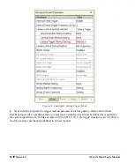
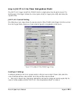
With the time integration setup click on the CamExpert Grab button to have a live acquisition in the
display window. Time integration can work either in free run or external trigger mode.
Modified and tested CamExpert settings, from this example or any custom configuration, should be
saved as a new camera configuration file with an appropriate description and unique file name.
Loading the saved camera file, either in CamExpert again or from your custom vision application, is
the simplest method to configure Sapera for the camera used.
Note on Analog Camera Timing Relationships
For analog cameras, the following formulas show the relationship between the PCLK parameter and
the Horizontal and Vertical total. These values must be accurate if the acquisition board drives the
synchronization signals to the camera (board is in Master Mode).
The HS and VS signal frequencies are:
total
freq
freq
H
*
PCLK
1
HS
1
total
freq
freq
V
*
HS
1
VS
1
Overview of Video Bandwidth and System Limitations
Some high resolution/high frame rate cameras can output more data than can be transferred through
the host computer’s PCI bus. A successful imaging application must account for the camera data
bandwidth and possibly control frame rate or image resolution to bring the bandwidth requirements to
within the system’s limitations.
Bandwidth is defined in two different ways. Peak bandwidth is the highest data rate occurring at any
time during the data transfer. The average bandwidth is the amount of data per unit of time being
transferred.
Each is calculated as follows:
Peak Bandwidth (MBps) = Pixel Clock Frequency *Bpp *nb channels
Average Bandwidth (MBps) = Frame Width *Frame Height *Frame Rate *Bpp
where:
MBps = Mega-Bytes per second
Bpp = Bytes per pixel
nb = number of …
When the bandwidth required by the frame grabber exceeds the capacity of the PCI 32/64-bit bus, the
following techniques can reduce and optimize the average bandwidth.


