X64-AN Quad User's Manual
Appendix: X-I/O Module Option
105
Opto-coupled Input: Electrical Details
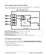
The two opto-coupled inputs can be used either with TTL or RS422 sources. A simplified input
schematic and important electrical specifications are listed below.
X-I/O Input
GND
Simplified
Opto-coupled
Input
typical 2 places
1
20
2
21
X-I/O Module
Opto-Coupled Input
DB37
Connector
In
In_Opto_1-
In
In_Opto_2-
Input reverse breakdown voltage
5 volts minimum
Maximum average forward input current
25 mA
Maximum input frequency
200 kHz
Maximum Sapera call-back rate
System processing dependent
TTL Input Electrical Details
The six TTL inputs are software configurable (see "Configuring User Defined Power-up I/O States"
on page 106) for standard TTL logic levels or industrial logic systems (typically 24 volts). The design
switch points are as follows:
TTL level mode: trip point at 2V +/- 5%
Industrial level mode: trip point at 16V +/- 5%

