Z-Trak2 3D Profiler Sensors
Appendix
•
139
Reference point, anchor point and offsets
Profiles are the result of the laser line reflected by the object surface and imaged by the 2D sensor.
Depending on where the line is located on the 2D image, height calculations can be made using
triangulation.
For each profiler model, reference points are defined: The profiler reference point and the anchor
point.
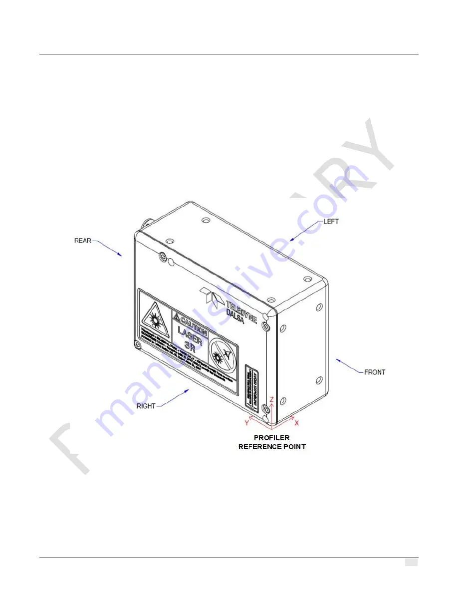
The profiler reference point is located at the bottom right corner of the front side of the profiler
body (the left side when looking at the front), as depicted below. This corner is on the lowest
mechanical edge of the profiler. It is the reference point relative to the unit itself.
Figure 35. The profiler reference point is located on the bottom right corner of the body, on the front side.
Looking AT the front, it will be on the left.
The anchor point is the origin (0, 0) of the 2D sensor image (DN range map); it is the reference
point for real-world measurements. Using these reference points, various X and Z real-world
offsets are calculated at calibration, which enable real-world measurements (see Figure 36-Figure
38). Each model has its own set of offsets, as depicted in the diagrams and tables below. Notice
the relative location of the X Ref offset relative to the X1 and X2 offsets in the three diagrams.


