Installation Guide
CONFIDENTIAL
TG-0057_19 TM4 SUMO HD CO300-A1_A2_A2.5 Installation Guide
© Dana TM4 inc., 2013-2020
Page 28 of 42
2020-11-20
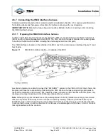
To install the harness on the motor and the MCU, turn the connector head until the pins are aligned with the
pinholes on the motor sensor interface. Once aligned, continue to turn the connector head until you hear a
click indicating that the head is locked in place: do not use force.
4.5.6.2
Motor sensor interface pinout information
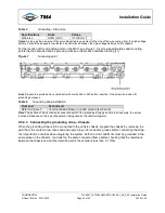
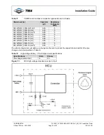
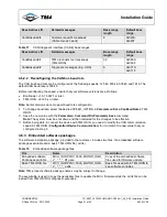
The following information may be required for troubleshooting purposes. Table 6 gives the mapping
between the pins on the TM4 motor and the TM4 MCU; Figure 10 shows the positions of the pins on the
connector head.
Table 6
Motor sensor interface pinout
Figure 10
Front of connector
TM4
MCU
Signal information
TM4
motor
A
Temperature C-
A
B
Temperature C+
B
C
Temperature B-
C
D
Temperature B+
D
E
Temperature A-
E
F
Temperature A+
F
G
Not to be connected
G
H
HVIL+
H
J
Resolver Exc (R1)
N
K
HVIL-
K
L
COS+ (S1)
L
M
COS- (S3)
M
N
SIN+ (S2)
J
P
SIN- (S4)
T
R
1 Wire+
R
S
1 Wire-
S
T
Resolver Excitation- (R2)
P
U
GND
U
V
Chassis
V


