Installation Guide
CONFIDENTIAL
TG-0057_19 TM4 SUMO HD CO300-A1_A2_A2.5 Installation Guide
© Dana TM4 inc., 2013-2020
Page 30 of 42
2020-11-20
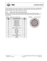
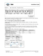
Figure 12
VMU interface harness – Plug pinout – P770E0160
Connector (front)
Wire insertion side (back)
Note
: The plug on the MCU has been uniquely keyed to prevent the harness from being incorrectly
connected.
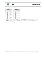
Table 7
VMU/ECU interface harness – Plug pinout specifications
Pin Signal names
Types
AWG
Descriptions
E
V
AUX
+
Power
20-22
Positive power wire of the MCU.
Must be connected to the auxiliary battery
using fuse type recommended in Table 14.
F
20-22
L
V
AUX
-(Chassis)
Reference
20-22
Must be connected to the vehicle chassis
(frame/auxiliary battery-).
M
20-22
G
IGNITION
Input
20-22
Enable signal to activate the MCU.
A
CAN1L
Communication
20-22
Low level of differential signal CAN1.
B
CAN1H
Communication
20-22
High level of differential signal CAN1.
C
CAN2L
Communication
20-22
Low level of differential signal CAN2.
D
CAN2H
Communication
20-22
High level of differential signal CAN2.
J
HVIL IN
HVIL IN
20-22
Hazardous voltage interlock loop signal.
K
HVIL OUT
HVIL OUT
20-22
Hazardous voltage interlock loop signal.
H
Emergency stop
Output
20-22
Emergency stop.
Notes:
1. Two supply pins (E and F) are used for redundancy but as they are physically connected in the MCU only one
correctly sized fuse is required to protect the VAUX supply in case of fault.
2. While designing the VMU/ECU interface harness, plan a connector or a mechanism to connect the diagnostic tool
(TM4 ODIN) to CAN1 or CAN2; see Section 4.5.10 for termination information.
3. Ensure that the VMU connector heads respect the IP6K9K ratings to prevent water infiltrating into the VMU if this is
required by the application.
4. There are no recommended wire colours.
5. For suggested safety circuit incorporating pins J, K and H, see Section 4.5.7.2.


