Installation Guide
CONFIDENTIAL
TG-0057_19 TM4 SUMO HD CO300-A1_A2_A2.5 Installation Guide
© Dana TM4 inc., 2013-2020
Page 34 of 42
2020-11-20
4.5.7.3 Installing the VMU interface harness assembly
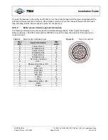
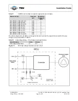
Use the plug pinout specifications given in Table 7 and Figure 12 and in the Kit-0076 assembly instructions
[7] to fabricate the appropriate VMU harness for your installation and then connect the VMU interface cable
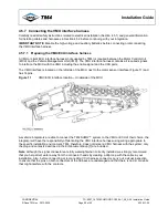
to the MCU using its dedicated mating location (Figure 11).
Before connecting or reconnecting the VMU interface harness connector, carry out a visual inspection to
ensure that the pins on both connectors of the harness are undamaged. Then, in order to protect the
electrical contacts against the surrounding environment, apply a contact lubricant (Electrolube CG60,
NyoGel 760G or equivalent) to the connector heads following the instructions provided by TM4 [9].
To install the harness on the MCU, turn the connector head until the pins are aligned with the pinholes on
the VMU interface. Once aligned, continue to turn the connector head until you hear a click indicating that
the head locked in place: do not use force to insert the connector head.
4.5.8 Connecting the high-voltage battery
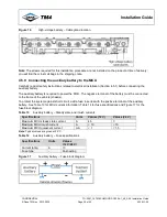
This section describes how to protect and safely connect the high-voltage battery to the MCU. If you are
going to prepare the cables or to adjust their length, refer to the cable and harness specification drawings
[13] for preparation and assembly instructions.
Note
: It is imperative that you are aware of the safety risks involved in connecting a high-voltage battery to
the system; before you start; refer to Section 4.5.8.1 for safety instructions and Section 4.5.2 for general
information on installing cables and harnesses before continuing with your integration.
4.5.8.1 Safety instructions related to connecting the high-voltage battery
Carefully read all safety instructions before connecting the high-voltage battery.
WARNINGS
This product generates high voltage that can cause an electric discharge or electrocution
resulting in injury or death.
When installing the product, verify that:
•
The traction battery (high-voltage battery) is disconnected.
•
The auxiliary battery (12 V/24 V battery) is disconnected.
The high-voltage cables MUST be shielded.
The external cables used for high voltage must be orange and shielded; the high voltage and level of
current delivered by this product can be lethal.
Failure to shield the high-voltage cables will result in non-compliance with EMI regulatory requirements.
Care must be taken when manipulating electrical equipment.
This product must be installed by qualified and authorized personnel in accordance with applicable
vehicle standards and industry practices. Always use appropriate insulation and protection before
manipulating the product even when the product is disconnected from a high-voltage source.
This product uses differential mode capacitors between the positive high-voltage DC bus (+) and
the negative high-voltage DC bus (-) and common mode capacitors between the high-voltage DC
bus and the chassis. Even when the product is disconnected from the high-voltage source, these
capacitors can hold a voltage high enough to cause an electric discharge or death.
It is important to ensure that no voltage is present on the high-voltage battery wires between both
polarities and from each polarity to chassis before manipulation.
Before opening the access panel, wait 10 minutes to ensure that internal MCU capacitors are discharged.
After that delay, the access panel can be opened and the MCU high-voltage battery inputs can be
measured between both polarities and from each polarity to chassis to ensure that no voltage is present.

