Installation Guide
CONFIDENTIAL
TG-0057_19 TM4 SUMO HD CO300-A1_A2_A2.5 Installation Guide
© Dana TM4 inc., 2013-2020
Page 35 of 42
2020-11-20
4.5.8.2 High-voltage battery short-circuit protection
The system requires a fuse on the HV DC bus. Proper fuse sizing is necessary to protect against reverse
polarity and short-circuit. TM4 recommends installing the following fuse:
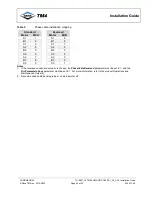
Table 9
High-voltage battery – Recommended fuse sizing
Specifications
Units
Values
Voltage rating
V
650
Current
A
600
Note
: The recommended fuse size corresponds to the highest acceptable value. A smaller fuse could be used as long
as it is correctly dimensioned in line with battery characteristics and able to protect both the MCU and the battery.
See the TM4 application note on SUMO Fuse and DC Cable Selection [6] for more information.
4.5.8.3 Internal common mode capacitors
There are 2 common mode capacitors installed internally in the MCU. If you need to verify that these
components are functioning correctly, measure the value from Vbatt+ to chassis or Vbatt- to chassis; this
measurement varies depending on the model of CO300 you are using:
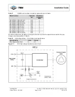
Table 10
CO300 model number vs internal common mode capacitor type
Model number
Capacitor
INV-HP2HV_0309-xx (A1)
INV-HP2HV_0309-03 (A2)
2.1 μF ± 20%
INV-HP2HV_0309-05 (A2.5)
INV-HP2HV_0309-16 (A2.5)
220 nF ± 20%
To ensure that the reading is precise, prior to taking the measurements, the DC lug screw must be installed
and tightened; the lug does not need to be installed.
Note
: The value given above is for reference purposes only; no action is required by the integrator.
4.5.8.4 High-voltage battery pre-charge circuit
The system requires a pre-charge circuit without which the system start-up sequence will fail and the MCU
may be permanently damaged. This pre-charge mechanism will protect the system from component stress
during each power-up thereby reducing the risk of damage to system components and promoting
component reliability.
Depending on the CO300 model used, the high-voltage battery input can have a capacitance of 945
μF or
645
μF
, both models with a resistance to chassis of 5M
Ω
. Figure 15 shows the schematic of the system
high-voltage battery input.
Characteristics of each inverter model are listed in Table 11. Model numbers are included in the information
on the label found on the product casing.


