Installation Guide
CONFIDENTIAL
TG-0057_19 TM4 SUMO HD CO300-A1_A2_A2.5 Installation Guide
© Dana TM4 inc., 2013-2020
Page 37 of 42
2020-11-20
4.5.8.5 High-voltage battery cable specifications
The high-voltage battery must be connected to the MCU using specific cable assemblies. Both 1/0 AWG
and 2/0 AWG cables are available; however, TM4 recommends using 2/0 AWG cable for optimum system
performance.
Refer to the cable drawings [13] and the system specifications [5] for the information required to select the
high-voltage cable best suited to your integration.
WARNING
The high-voltage cables MUST be shielded.
The external cables used for high voltage must be orange and shielded; the high voltage and level of
current delivered by this product can be lethal.
Failure to shield the high-voltage cables will result in non-compliance with EMI regulatory requirements.
4.5.8.6 Preparing high-voltage battery cables
The high-voltage battery cables must be prepared by the integrator before installing them in the MCU.
Refer to the cable end specifications [12] for preparation instructions for both the negative and positive
cable ends.
4.5.8.7 Installing the high-voltage battery cables
Before installing the high-voltage battery cables, refer to the general warnings and safety instructions in
Section 4.5.8.1 and in this section.
WARNING
Risk of electrocution.
The high-voltage power source must not be connected until the installation is completed and the plugs are
firmly attached.
WARNING
Overtightening the screws/plugs may damage the product.
•
The maximum recommended torque given in the product interface drawing is for final cable
installation; if you insert the screws without the lugs, hand-tighten the screws lightly to prevent
damage to the product).
•
We recommend that you protect or cushion the end of the tool used to tighten the plugs to prevent
scratching the casing.
Using the harness you have prepared or purchased from TM4, refer to the product interface drawing [11]
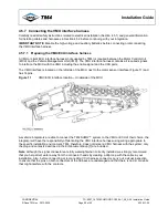
and cable harness specification [13] for illustrated installation information. See Figure 16 for the location of
the high-voltage connectors on the MCU casing.


