Installation Guide
CONFIDENTIAL
TG-0057_19 TM4 SUMO HD CO300-A1_A2_A2.5 Installation Guide
© Dana TM4 inc., 2013-2020
Page 24 of 42
2020-11-20
Table 3
Grounding – Strap size
Specifications
Units
Values
Wire size
AWG (mm
2
)
1/0 (50 mm
2
)
Notes:
As long as the wire size of the grounding strap is equivalent to the size of the wire coming from the high-voltage
battery, it should be adequate to withstand a short circuit between the high-voltage battery and the chassis.
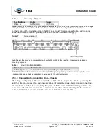
For the location of the grounding point on the MCU, see Figure 7; for screw specifications and mounting
points that can also be used as ground points, see the product interface drawing [11].
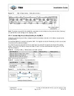
Figure 7
Grounding point
Note:
Prepare the provided zinc-coated bolt with Loctite 242 or 243 before insertion. One screw is provided for
grounding purposes.
Table 4
Grounding strap installation
First end
Second end
Refer to Figure 7
Vehicle chassis (frame) or earth ground (test bench)
Note:
The location of the second end connection point of the grounding strap given here is an example; the actual
location will depend on the type of application being used by the vehicle integrator.
4.5.4.3 Connecting the grounding strap – Chassis
When the grounding strap is to be connected to the vehicle chassis, prepare the chassis by removing the
paint from the contact area, then sand and apply a layer of conductive grease before connecting the strap.
It is important to note that when integrating the system, both the motor and MCU must be grounded in the
same place on the chassis, or at least on the same connected frame before checking that the resistance
between the chassis and another metallic part of the vehicle is less than 0.1 Ohm.


